
1 | P a g e
Embedded Host
High Speed Electrical Test Procedure
Revision 1.01
December 2018

2 | P a g e
Table of content
1. Reference .................................................................................................................. 3
2. Background ................................................................................................................ 3
3. Test Mode Support .................................................................................................... 4
3.1 Setup ........................................................................................................................................ 4
3.2 USB High Speed PID definitions ..................................................................................................... 6
3.3 Test mode details .......................................................................................................................... 6
3.4 Test mode implementation ........................................................................................................... 8
3.5 High Speed Embedded Host Tester (PID/VID) ............................................................................... 8
4. Test Procedure ........................................................................................................... 9
4.1 High Speed Signal Quality (EL_2, EL_3, EL_6, EL_7) ...................................................................... 9
4.2 Host Controller Packet Parameters (EL_21, EL_22, EL_23, EL_25, EL_55) .................................. 12
4.3 Host Chirp Timing (EL_33, EL_34, EL_35) .................................................................................... 17
4.4 Host Suspend/Resume (EL_39, EL_41) ........................................................................................ 19
4.5 Host Test_J (EL_8, EL_9) .............................................................................................................. 21
4.6 Host Test_K (EL_8, EL_9) ............................................................................................................. 22
4.7 Host Test_SE0_NAK (EL_8, EL_9)................................................................................................. 23
5. Fill out form ............................................................................................................. 24

3 | P a g e
1. Reference
Standard
Description
Revision
Status
USB 2.0 Spec
USB 2.0 Specification with ECN
2.0
Released
OTG & EH
Supplement 2.0
OTG & EH
Compliance Plan
2. Background
In order to perform USB 2.0 High Speed electrical tests a High Speed product must support test
modes as defined in section 7.1.20 of the USB 2.0 specification.
To active a test mode, the USB 2.0 Specification defines the SetFeature() command as the desired
interface. The USB-IF offers for free a High Speed electrical Test Tool (HSET) which is Windows based,
to activate the various test modes and operations.
Problem is that HSET only runs on Windows based PC systems and cannot be used for High Speed
USB hosts that not run Windows PC systems.
The solution for this problem is that the “On-The-Go and Embedded Host Supplement to the USB
Revision 2.0 Specification” defines a method in entering the required high speed electrical test
modes.
USB 3.0 Super Speed Embedded host that support USB 2.0 High Speed should follow the same
guidelines as described in this document.
It’s important that non-windows based host vendors implement these test modes.
Beside the High Speed electrical test an embedded host also must pass other tests as defined at:
http://testusb.com/Ehost_test.htm
This document only describe the High Speed electrical tests.
4 | P a g e
3. Test Mode Support
3.1 Setup
3.1.1 PIDVID
Details on the PIDVID can be found at www.testusb.com
3.1.2 USB-IF setup
The USB-IF logo compliance require to use the USB-IF approved test fixtures for the High Speed EYE
diagram. Reason for only using these fixture is that that there are differences reported between all
fixtures available on the market. When measuring the USB-IF High Speed EYE only use direct SMA
probing and no active differential probing.
SMA probing
5 | P a g e
3.1.2.1 Host with A-Receptacle
When the host use A-receptacles use the USB-IF fixture.
The USB-IF fixtures can be purchased via the USB-IF eStore at: http://www.usb.org
Do note that the USB-IF fixture is only able in measuring the High Speed Eye diagram and therefore it
is still required to use the other fixtures that can be found for example at www.testusb.com for the
remaining high speed electrical tests.
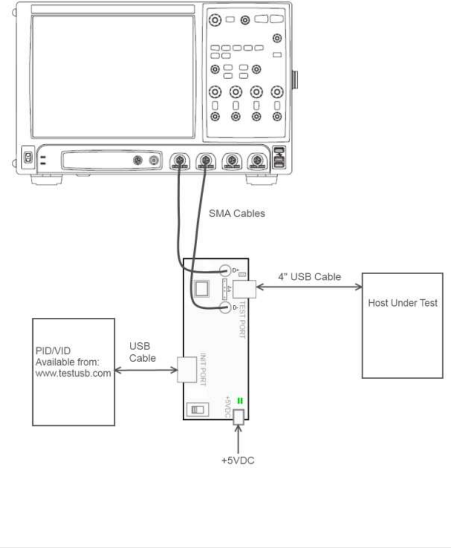
3.1.2.2 Host with Type-C™ Receptacle
When the host use Type-C™ receptacles use the approved Type-C™ fixtures like the TestUSB fixtures
FS-HUCP and FS-HUCR.
These fixtures can be can be purchased via www.testusb.com

6 | P a g e
3.1.3 Micro AB setup
OTG products and some Embedded Hosts have a micro AB receptacle. For those product a short
adapter with mirco-A plug to standard A-receptacle is required.
If the product is an OTG product the micro-A plug will force it to host mode there it has the ID-pin to
GND.
3.2 USB High Speed PID definitions
The VID is 0x1A0A. The PIDs presented by the PID/VID corresponds with the following test modes.
PID
Test Mode
0x0101
TEST_SE0_NAK
0x0102
TEST_J
0x0103
TEST_K
0x0104
TEST_PACKET
0x0105
RESERVED
0x0106
HS_HOST_PORT_SUSPEND_RESUME
0x0107
SINGLE_STEP_GET_DEV_DESC
0x0108
SINGLE_STEP_SET_FEATURE
0x0200
TTST_CONFIG
0x0201
Unknown Device Not Supporting HNP
0x0202
Unknown Device Supporting HNP
3.3 Test mode details
High-speed Electrical Test Mode Support
All USB-IF high-speed host electrical compliance tests shall be performed on high-speed hosts. These
high-speed tests utilize the test modes defined in Section 7.1.20 of [USB2.0]. An OTG device or EH
shall support the test device that initiates these test modes. Upon enumeration by the host, the test
device presents a VID/PID pair that defines a test mode or operation to execute. Upon enumerating
the test device with VID of 0x1A0A, the Targeted Host shall perform the following operations based
on the PID presented. The test mode or operation shall occur on the port where the test fixture is
attached. The test devices shall continue to be recognized by retail examples of the devices, to
permit subsequent audit.
Test_SE0_NAK
Upon enumerating VID 0x1A0A/PID 0x0101, the hosts downstream port shall enter a high-speed
receive mode as described in Section 7.1.20 [USB2.0] and drives an SE0 until the controller is reset.

7 | P a g e
Test_J
Upon enumerating VID 0x1A0A/PID 0x0102, the host’s downstream port shall enter a high-speed J
state as described in Section 7.1.20 of [USB2.0] until the host controller is reset.
Test_K
Upon enumerating VID 0x1A0A/PID 0x0103, the host’s downstream port shall enter a high-speed K
state as described in Section 7.1.20 of [USB2.0] until the host controller is reset.
Test_Packet
Upon enumerating VID 0x1A0A/PID 0x0104, the host shall begin sending test packets as described in
Section 7.1.20 of [USB2.0] until the host controller is reset.
HS_HOST_PORT_SUSPEND_RESUME
Upon enumerating VID:0x1A0A/PID 0x0106, the host shall continue sending SOFs for 15 seconds,
then suspend the downstream port under test per Section 7.1.7.6.1 of [USB2.0]. After 15 seconds has
elapsed, the host shall issue a ResumeK state on the bus, then it will continue sending SOFs.
SINGLE_STEP_GET_DEVICE_DESCRIPTOR
When the host discovers a device with VID 0x1A0A/PID 0x0107, the following steps are executed by
the host and the device.
1. The host enumerates the test device, reads VID 0x1A0A/PID 0x0107, then completes its
enumeration procedure.
2. The host issues SOFs for 15 seconds allowing the test engineer to raise the scope trigger just above
the SOF voltage level.
3. The host sends a complete GetDescriptor(Device) transfer
4. The device ACKs the request, triggering the scope. (Note: SOFs continue.)
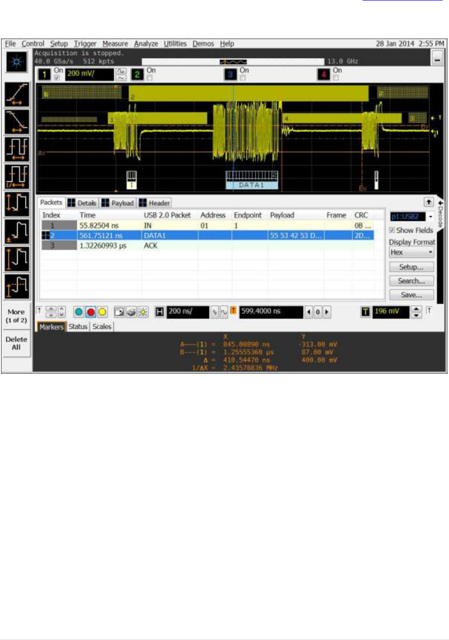
SINGLE_STEP_GET_DEVICE_DESCRIPTOR_DATA
When the host discovers a device with VID 0x1A0A/PID 0x0108, the following steps are executed by
the host and the device.
1. The host enumerates the test device and reads VID 0x1A0A/PID 0x0108, then completes its
enumeration procedure
2. After enumerating the device, the host sends GetDescriptor(Device)
3. The device ACKs the request
4. The host issues SOFs for 15 seconds allowing the test engineer to raise the scope trigger just above
the SOF voltage level
5. The host sends an IN packet
6. The device sends data in response to the IN packet, triggering the scope
7. The host sends an ACK in response to the data. (Note: SOFs may follow the IN transaction).

8 | P a g e
Unknown Device Not Supporting HNP (not an electrical test)
A device with VID=0x1A0A, PID=0x0201 is reserved as a test device, which shall not be on the TPL of
any Targeted Host. It may be used by the compliance tester to represent a device which is not
supported and which does not support HNP. Vendors should note that the compliance tester may
use this, or any other VID/PID combination which is not on the TPL, for the purposes of tests which
require compliant behavior when encountering such a device.
Unknown Device Supporting HNP (not an electrical test)
A device with VID=0x1A0A, PID=0x0202 is reserved as a test device, which shall not be on the TPL of
any Targeted Host. It may be used by the compliance tester to represent a device which is not
supported and which supports HNP. Vendors should note that the compliance PET may use this, or
any other VID/PID combination which is not on the TPL, for the purposes of tests which require
compliant behavior when encountering such a device.
3.4 Test mode implementation
Windows PC systems can use the USB.ORG tool USBHSET for the High Speed electrical tests but USB
hosts that run another OS’s will require to implement a VID, PID detection. Upon detecting the VID
PID as in the above chapter 4.3 the host will have to behave accordingly.
Appendix A give some details how this should be implemented for Linux variants.
For updates and more details please check www.testusb.com
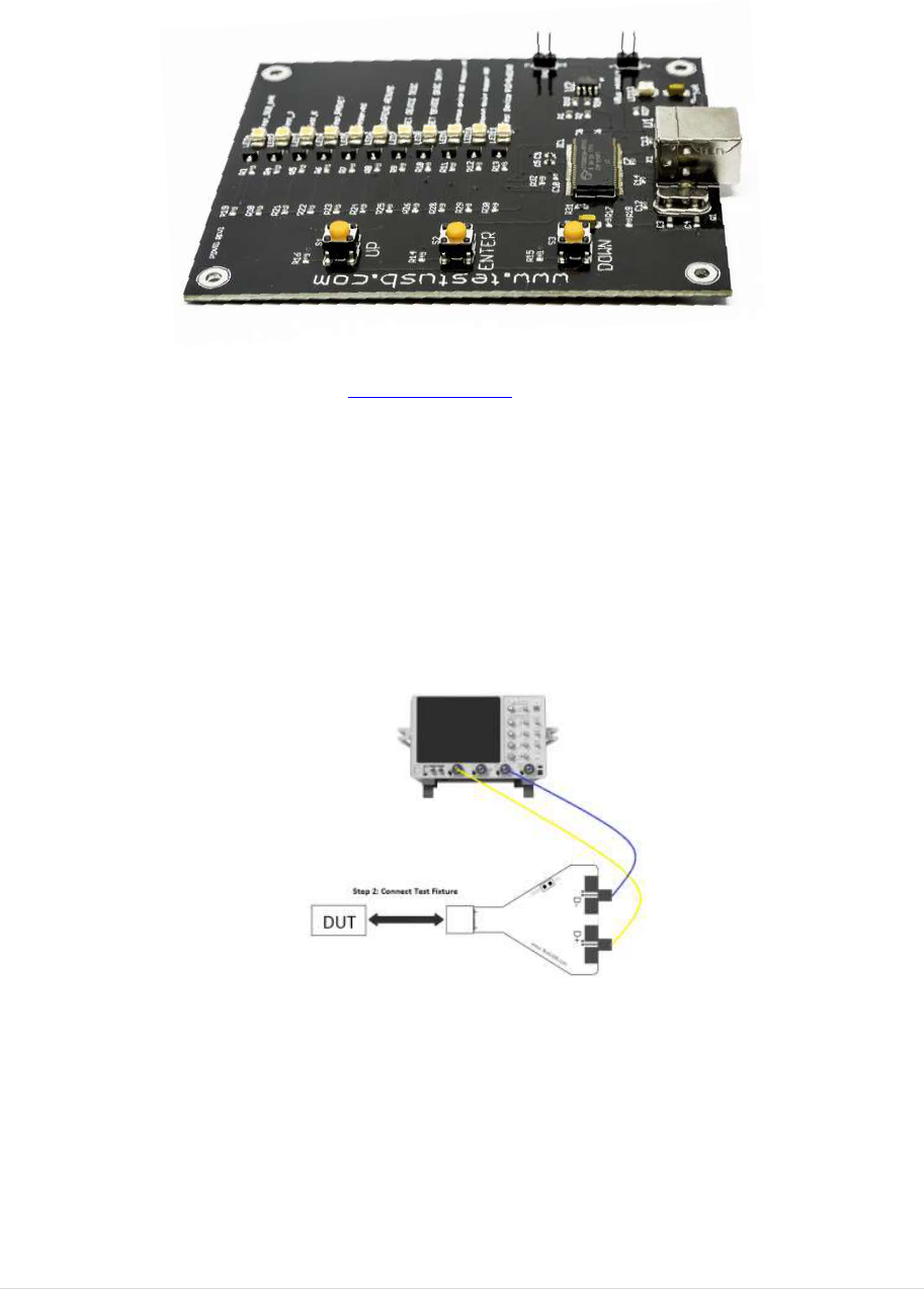
3.5 High Speed Embedded Host Tester (PID/VID)
In order to send the required VID and PID the High Speed Embedded Host Tester (PID/VID) of
www.testusb.com can be used. With this small bus powered device you select the required test
mode with the selection switch and plug it into the High Speed embedded Host. Between the EHost
and PID/VID the high speed host test fixture is connected in order to make it possible to probe the
signals.
9 | P a g e
4. Test Procedure
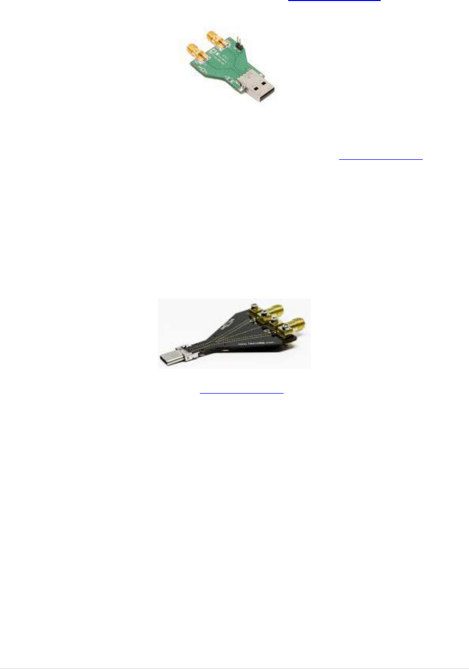
4.1 High Speed Signal Quality (EL_2, EL_3, EL_6, EL_7)
This test is measuring the downstream near end Signal Quality (EYE diagram). For this test the host
need to send out the Test_Packet as defined in section 7.1.20 of the USB 2.0 specification. The USB-IF
tool USBET will make the required analyses.
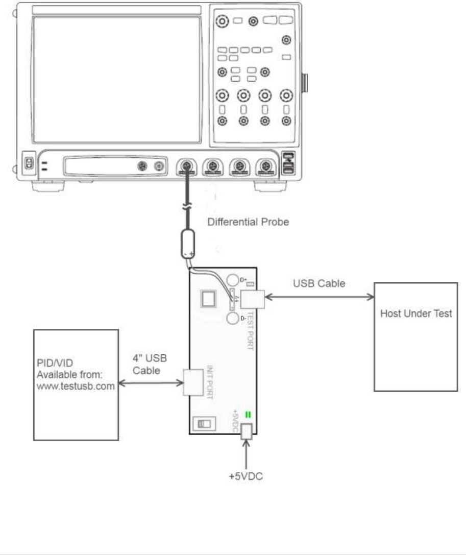
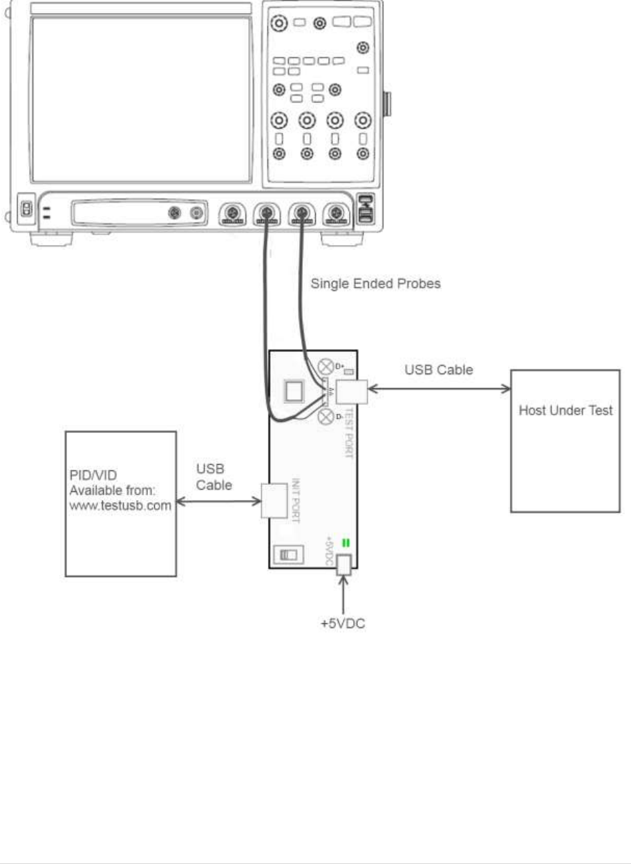
Test Setup:
10 | P a g e
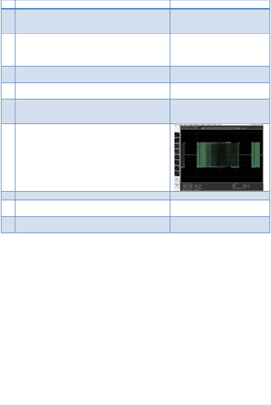
Test Procedure Keysight fixture:
Test Fixture & PID/VID
EHost
1
Apply power to the test fixture and put test fixture
switch test mode off. LED power illuminate (Green
LED), Test mode not (Orange LED)
2
Attach the two SMA cables to the fixture with the D+ to
Channel 1 and D- to Channel 3 of the Scope and make
the scope settings accordingly. For the differential
signal subtract Channel 1 with Channel 3.
3
Connect a short USB cable from the Test port of the
fixture to the Embedded Host under test.
4
Connect PID/VID and select with UP or DOWN
Test_Packet and press Enter.
5
Host enumerates the PID/VID and
responds to send continuously
Test_Packet
6
Flip the switch of the test fixture that switches the
termination on. LED power and Test mode illuminate
(Orange LED lit).
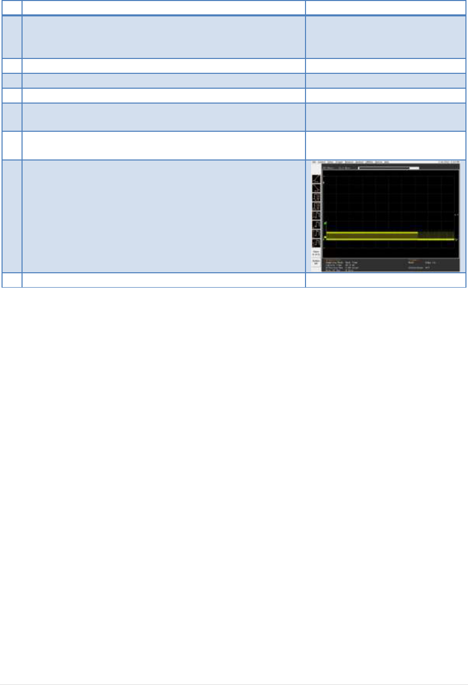
7
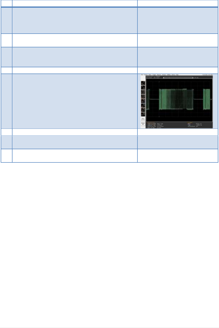
Scope will capture the packet.
8
Scope will analyze and calculate the parameters with
USBET. (EL_2, EL_3, EL_6, EL_7)
9
If there are more ports available repeat the test for the
remaining downstream ports.
A power cycle of the host is required in order to proceed.
11 | P a g e
Test Procedure USB-IF fixture:
Test Fixture & PID/VID
EHost
1
Attach the two SMA cables to the fixture with the D+ to
Channel 1 and D- to Channel 3 of the Scope and make
the scope settings accordingly. For the differential
signal subtract Channel 1 with Channel 3.
2
Connect PID/VID and select with UP or DOWN
Test_Packet and press Enter.
3
Host enumerates the PID/VID and
responds to send continuously
Test_Packet
4
Remove PID/VID
5
Connect fixture to embedded host
6
Scope will capture the packet.
7
Scope will analyze and calculate the parameters with
USBET. (EL_2, EL_3, EL_6, EL_7)
8
If there are more ports available repeat the test for the
remaining downstream ports.
A power cycle of the host is required in order to proceed.
12 | P a g e
4.2 Host Controller Packet Parameters (EL_21, EL_22, EL_23, EL_25, EL_55)
The test will measure the sync field (EL_21) EOP field (EL_25), EOP field of SOF (EL_55), the delay
between two host packets (EL_23) and the response time of a host to a device packet (EL_22)
Test Procedure:
This test is split up into two sub-tests.
4.2.1. SINGLE_STEP_DEV_DESC (EL_21, EL_25, EL_23)
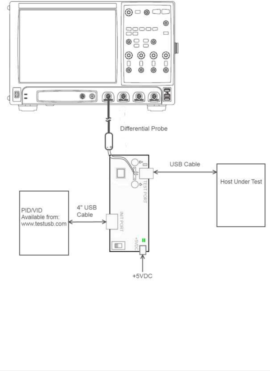
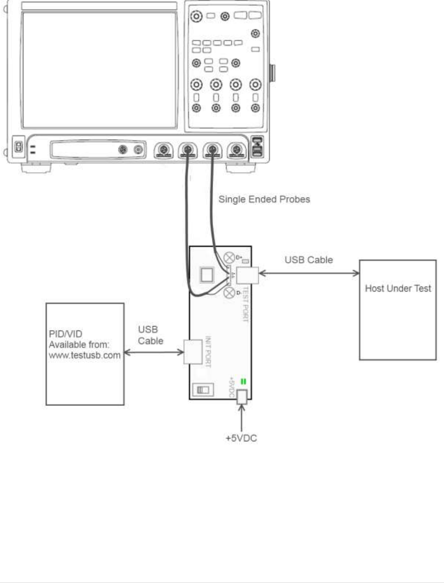
Test Setup:

13 | P a g e
Test Fixture & PID/VID
EHost
1
Apply power to the test fixture and put test fixture
switch test mode off. LED power illuminate (Green
LED), Test mode not (Orange LED)
2
Terminate the SMA probing points with 50Ohm.
3
Connect the differential probe to TP2. With the + of the
probe to D+.
4
Connect a long USB cable (*) from the Test port of the
fixture to the Embedded Host under test.
5
Connect PID/VID and select with UP or DOWN
SINGLE_STEP_GET_DEVICE_DESCRIPTOR and press
Enter.
6
Host enumerates the PID/VID and
responds to send SOFs for 15
seconds.
7
Verify SOFs are send and increase the scope amplitude
trigger level until SOFs are no longer triggered. (*)
8
After 15 seconds of SOFs the host
initiates the setup phase of the
GetDescriptor() command. The
host sends SETUP and DATA. (first
and second packet)
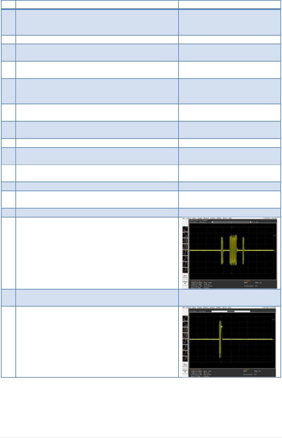
9
The PID/VID sends an ACK as response. The scope
triggers on this ACK.
10
The host packets are the first two packets. Measure the
sync field (EL_21) EOP field (EL_25) on the first two
packets and measure the time between those two
(EL_23) packets.
(*) In order to differentiate host and device packets we use the voltage drop of the cable. The longer
the cable between the test fixture and embedded host the lower the amplitude of the embedded
host packet. Between the PID/VID and fixture we use a short cable since we want to trigger on device
packet with higher amplitude. It’s also possible to make another trigger method and not trigger on
14 | P a g e
voltage amplitude different. In that case ignore step 8 (EL_23) and step 10 (EL_22).
4.2.2. SINGLE_STEP_SET_FEATURE (EL_22, EL_55)
Test Setup:
15 | P a g e
Test Fixture & PID/VID
EHost
1
Apply power to the test fixture and put test fixture
switch test mode off. LED power illuminate (Green LED),
Test mode not (Orange LED)
2
Terminate the SMA probing points with 50Ohm.
3
Connect the differential probe to TP2. With the + of the
probe to D+.
4
Connect a long USB cable from the Test port of the
fixture to the Embedded Host under test. (*)
5
Connect PID/VID and select with UP or DOWN
SINGLE_STEP_GET_DEVICE_DESCRIPTOR and press
Enter.
6
Connect with a short USB cable the PID/VID to the
Initialize port.
7
The host enumerates the PID/VID
and request GetDescriptor()
8
PID/VID send ACK
9
The host sends for 15 seconds
SOFs
10
Verify SOFs are send and increase the scope amplitude
trigger level until SOFs are no longer triggered.
11
Host issues an IN
12
PID/VID send DATA (second packet) that trigger the
scope.
13
Host send an ACK (third packet)
14
EL_22 Measure the time between DATA (second) and
ACK (third)
15
Lower the trigger level of the scope so it triggers on
SOFs.
16
EL_55 Measure the EOP of the SOF packet.
Comments:
EL_22 can be difficult to measure there the test mode is often wrongly implemented by the
embedded host vendor. Therefore if it not work you may want to try to capture the packets on real
life communication between a TPL devices and embedded host by inserting the device. Make sure
that the cable between the TPL device and test fixture is short while the cable between the fixture
16 | P a g e
and embedded host is long (preferred 5m). The difference in cable length is to distinguish the
difference between host and device packets.
It may be required to disconnect and re-connect more than once in order to trigger properly. If the
scope used is have infiniiScan software you can download the trigger setting from www.testusb.com
Do note that you should take an additional delay of 60ns for 5m cable.
17 | P a g e
4.3 Host Chirp Timing (EL_33, EL_34, EL_35)
Any known good high speed device can be used for this test. When using the Embedded Host tester
it’s advisable to not select a Test_Mode there it requires to power cycle the host.
Test Setup:
18 | P a g e
Test Procedure:
Test Fixture & PID/VID
EHost
1
Apply power to the test fixture and put test fixture switch
test mode off. LED power illuminate (Green LED), Test
mode not (Orange LED)
2
Terminate the SMA probing points with 50Ohm.
3
Connect the single-ended probe of channel 1 to D+ of TP2.
4
Connect the single-ended probe of channel 2 to D- of TP2.
5
Connect a USB cable from the Test port of the fixture to
the Embedded Host under test.
6
Connect any known good high speed device to the Initialize
port.
The Host and device do the Chirp negotiation
7
Scope will measure the EL_33, EL_34, EL_35
19 | P a g e
4.4 Host Suspend/Resume (EL_39, EL_41)
It’s not mandatory for an embedded host to support suspend, if the embedded host not support
suspend, suspend and resume test should not be performed.
This test verifies if the embedded host enters the suspend state and resumes.
Test Setup:

20 | P a g e
Test Procedure:
Test Fixture & PID/VID
EHost
1
Apply power to the test fixture and put test fixture switch
test mode off. LED power illuminate (Green LED), Test
mode not (Orange LED)
2
Terminate the SMA probing points with 50Ohm.
3
Connect the single-ended probe of channel 1 to D+ of TP2.
4
Connect the single-ended probe of channel 2 to D- of TP2.
5
Connect a USB cable from the Test port of the fixture to
the Embedded Host under test.
6
Connect PID/VID and select with UP or DOWN
HS_HOST_PORT_SUSPEND_RESUME and press Enter.
7
Host enumerates the PID/VID
and responds to send SOFs for 15
seconds.
8
After 15 seconds the host port will enter suspend state
9
After 15 seconds of suspend
state the host shall issue a
ResumeK state on the bus, then
continue sending SOFs.
21 | P a g e
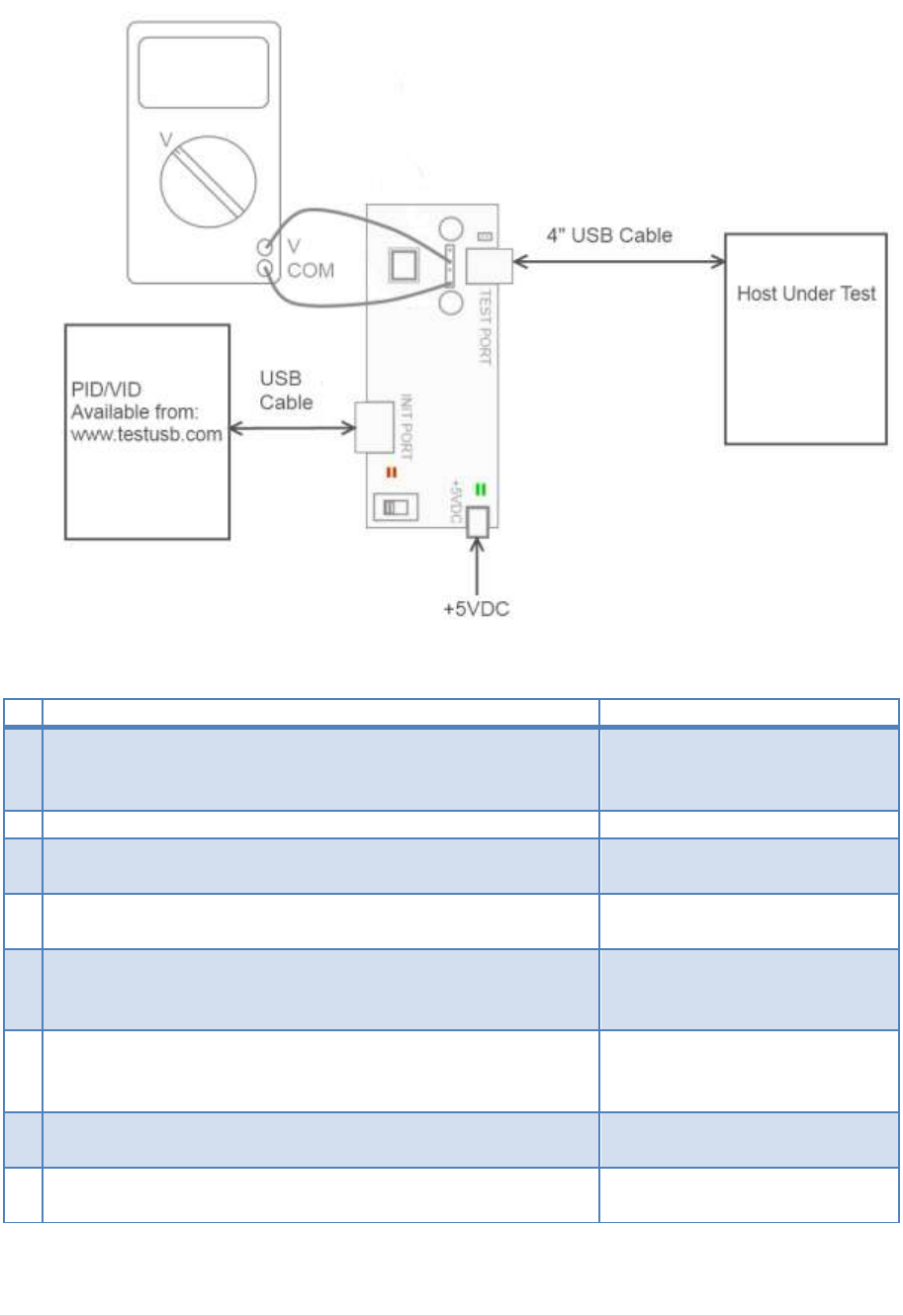
4.5 Host Test_J (EL_8, EL_9)
Test Setup:
Test Procedure:
Test Fixture & PID/VID
EHost
1
Apply power to the test fixture and put test fixture switch
test mode off. LED power illuminate (Green LED), Test mode
not (Orange LED)
2
Terminate the SMA probing points with 50Ohm.
3
Connect a short USB cable from the Test port of the fixture
to the Embedded Host under test.
4
Connect PID/VID and select with UP or DOWN Test_J and
press Enter.
5
Host enumerates the PID/VID
and shall enter a high-speed J
state. (D+ high ; D- low)
6
Flip the switch of the test fixture that switches the
termination on. LED power and Test mode illuminate
(Orange LED lit).
7
Measure with a DC Voltmeter the voltage between D+ and
GND.
8
Measure with a DC Voltmeter the voltage between D- and
GND
A power cycle of the host is required in order to proceed.
22 | P a g e
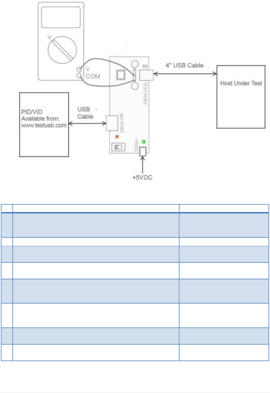
4.6 Host Test_K (EL_8, EL_9)
Test Setup:
Test Procedure:
Test Fixture & PID/VID
EHost
1
Apply power to the test fixture and put test fixture switch
test mode off. LED power illuminate (Green LED), Test mode
not (Orange LED)
2
Terminate the SMA probing points with 50Ohm.
3
Connect a short USB cable from the Test port of the fixture
to the Embedded Host under test.
4
Connect PID/VID and select with UP or DOWN Test_K and
press Enter.
5
Host enumerates the PID/VID
and shall enter a high-speed K
state. (D+ low ; D- high)
6
Flip the switch of the test fixture that switches the
termination on. LED power and Test mode illuminate
(Orange LED lit).
7
Measure with a DC Voltmeter the voltage between D+ and
GND
8
Measure with a DC Voltmeter the voltage between D- and
GND
A power cycle of the host is required in order to proceed.

23 | P a g e
4.7 Host Test_SE0_NAK (EL_8, EL_9)
Test Setup:
Test Procedure:
Test Fixture & PID/VID
EHost
1
Apply power to the test fixture and put test fixture switch
test mode off. LED power illuminate (Green LED), Test mode
not (Orange LED)
2
Terminate the SMA probing points with 50Ohm.
3
Connect a short USB cable from the Test port of the fixture
to the Embedded Host under test.
4
Connect PID/VID and select with UP or DOWN
Test_SE0_NAK and press Enter.
5
Host enumerates the PID/VID
and shall drive an SE0 state.
(D+ low; D- low)
6
Flip the switch of the test fixture that switches the
termination on. LED power and Test mode illuminate
(Orange LED lit).
7
Measure with a DC Voltmeter the voltage between D+ and
GND
8
Measure with a DC Voltmeter the voltage between D- and
GND
A power cycle of the host is required in order to proceed.

24 | P a g e
5. Fill out form
ID
Test
Requirement
Measured Value
Status
EL_2
High-Speed
transmitter data rate
480 Mb/s +-0.05%
Mb/s
Pass/Fail
EL_3
Data Eye and Mask
Test
Not touch near end
EYE
Number EYE hits
Pass/Fail
EL_6
Rise and fall times
> 500 ps (*)
ps
Pass/Fail
EL_7
Monotonic edge
Data transition is
monotonic
Pass/Fail
EL_21
Sync Field Length Test
(**)
ns
Pass/Fail/NA
EL_25
EOP Length Test
(**)
ns
Pass/Fail/NA
EL_23
Inter-packet Gap
Between First 2 host
Packets (Host – Host)
(**)
ns
Pass/Fail/NA
EL_22
Inter-packet Gap of a
host to a device packet
(Device – Host)
(**)
ns
Pass/Fail
EL_55
SOF EOP Width Test
(**)
ns
Pass/Fail
EL_33
CHIRP Timing
Response
1ns to 100µs
µs
Pass/Fail
EL_34
CHIRP J K Width
40µs to 60µs
µs
Pass/Fail
EL_35
SOF Timing Response
100µs to 500µs
µs
Pass/Fail
EL_39
Suspend
Enter suspend
Pass/Fail/NA
EL_41
Resume
< 3ms
Pass/Fail/NA
EL_8
Host J Test
Driven data line
400mV +-10% (***)
Non driven data lines
max 10mV
D+: mV
D-: mV
Pass/Fail
EL_8
Host K Test
Driven data line
400mV +-10% (***)
Non data driven lines
max 10mV
D+: mV
D-: mV
Pass/Fail
EL_9
Host SE0_NAK Test
Non data driven lines
max 10mV
D+: mV
D-: mV
Pass/Fail
(*) EL_6 waiver low as 100ps:
http://compliance.usb.org/index.asp?UpdateFile=Electrical&Format=Standard#87
(**) EL_22 for products with an internal hub to the embedded host may have an additional delay:
http://compliance.usb.org/index.asp?UpdateFile=Electrical&Format=Standard#43
One HS Hub may truncate up to 4 bits of the sync field and add up to 4 bits to the EOP.
(***) EL_8 only the non-driven lines are pass / fail criteria
http://compliance.usb.org/index.asp?UpdateFile=Electrical&Format=Standard#67
http://compliance.usb.org/index.asp?UpdateFile=Electrical&Format=Standard#92
