
Oracle
®
Fusion Cloud EPM
Designing with Financial Reporting Web
Studio for Oracle Enterprise Performance
Management Cloud
E96246-22
Oracle Fusion Cloud EPM Designing with Financial Reporting Web Studio for Oracle Enterprise Performance
Management Cloud,
E96246-22
Copyright
©
2016, 2023, Oracle and/or its affiliates.
Primary Author: EPM Information Development Team
This software and related documentation are provided under a license agreement containing restrictions on
use and disclosure and are protected by intellectual property laws. Except as expressly permitted in your
license agreement or allowed by law, you may not use, copy, reproduce, translate, broadcast, modify, license,
transmit, distribute, exhibit, perform, publish, or display any part, in any form, or by any means. Reverse
engineering, disassembly, or decompilation of this software, unless required by law for interoperability, is
prohibited.
The information contained herein is subject to change without notice and is not warranted to be error-free. If
you find any errors, please report them to us in writing.
If this is software, software documentation, data (as defined in the Federal Acquisition Regulation), or related
documentation that is delivered to the U.S. Government or anyone licensing it on behalf of the U.S.
Government, then the following notice is applicable:
U.S. GOVERNMENT END USERS: Oracle programs (including any operating system, integrated software,
any programs embedded, installed, or activated on delivered hardware, and modifications of such programs)
and Oracle computer documentation or other Oracle data delivered to or accessed by U.S. Government end
users are "commercial computer software," "commercial computer software documentation," or "limited rights
data" pursuant to the applicable Federal Acquisition Regulation and agency-specific supplemental
regulations. As such, the use, reproduction, duplication, release, display, disclosure, modification, preparation
of derivative works, and/or adaptation of i) Oracle programs (including any operating system, integrated
software, any programs embedded, installed, or activated on delivered hardware, and modifications of such
programs), ii) Oracle computer documentation and/or iii) other Oracle data, is subject to the rights and
limitations specified in the license contained in the applicable contract. The terms governing the U.S.
Government's use of Oracle cloud services are defined by the applicable contract for such services. No other
rights are granted to the U.S. Government.
This software or hardware is developed for general use in a variety of information management applications.
It is not developed or intended for use in any inherently dangerous applications, including applications that
may create a risk of personal injury. If you use this software or hardware in dangerous applications, then you
shall be responsible to take all appropriate fail-safe, backup, redundancy, and other measures to ensure its
safe use. Oracle Corporation and its affiliates disclaim any liability for any damages caused by use of this
software or hardware in dangerous applications.
Oracle
®
, Java, and MySQL are registered trademarks of Oracle and/or its affiliates. Other names may be
trademarks of their respective owners.
Intel and Intel Inside are trademarks or registered trademarks of Intel Corporation. All SPARC trademarks are
used under license and are trademarks or registered trademarks of SPARC International, Inc. AMD, Epyc,
and the AMD logo are trademarks or registered trademarks of Advanced Micro Devices. UNIX is a registered
trademark of The Open Group.
This software or hardware and documentation may provide access to or information about content, products,
and services from third parties. Oracle Corporation and its affiliates are not responsible for and expressly
disclaim all warranties of any kind with respect to third-party content, products, and services unless otherwise
set forth in an applicable agreement between you and Oracle. Oracle Corporation and its affiliates will not be
responsible for any loss, costs, or damages incurred due to your access to or use of third-party content,
products, or services, except as set forth in an applicable agreement between you and Oracle.

Documentation Accessibility
For information about Oracle's commitment to accessibility, visit the Oracle
Accessibility Program website at http://www.oracle.com/pls/topic/lookup?
ctx=acc&id=docacc.
Access to Oracle Support
Oracle customers that have purchased support have access to electronic support
through My Oracle Support. For information, visit http://www.oracle.com/pls/topic/
lookup?ctx=acc&id=info or visit http://www.oracle.com/pls/topic/lookup?ctx=acc&id=trs
if you are hearing impaired.
Documentation Accessibility
iv

Documentation Feedback
To provide feedback on this documentation, click the feedback button at the bottom of the
page in any Oracle Help Center topic. You can also send email to [email protected].
v

1
Creating and Running an EPM Center of
Excellence
A best practice for EPM is to create a CoE (Center of Excellence).
An EPM CoE is a unified effort to ensure adoption and best practices. It drives transformation
in business processes related to performance management and the use of technology-
enabled solutions.
Cloud adoption can empower your organization to improve business agility and promote
innovative solutions. An EPM CoE oversees your cloud initiative, and it can help protect and
maintain your investment and promote effective use.
The EPM CoE team:
• Ensures cloud adoption, helping your organization get the most out of your Cloud EPM
investment
• Serves as a steering committee for best practices
• Leads EPM-related change management initiatives and drives transformation
All customers can benefit from an EPM CoE, including customers who have already
implemented EPM.
How Do I Get Started?
Click to get best practices, guidance, and strategies for your own EPM CoE: Introduction to
EPM Center of Excellence.
Learn More
• Watch the Cloud Customer Connect webinar: Creating and Running a Center of
Excellence (CoE) for Cloud EPM
• Watch the videos: Overview: EPM Center of Excellence and Creating a Center of
Excellence.
• See the business benefits and value proposition of an EPM CoE in Creating and Running
an EPM Center of Excellence.
1-1

Chapter 1
1-2

Part I
Overview of Financial Reporting Web Studio
Related Topics
• About Financial Reporting Web Studio
Financial Reporting Web Studio is a web-based report authoring solution.
• Services That Use Financial Reporting Web Studio
Several services use Financial Reporting Web Studio.
• Accessing Financial Reporting Web Studio
Open Financial Reporting Web Studio to design reports.
About Financial Reporting Web Studio
Financial Reporting Web Studio is a web-based report authoring solution.
Similar in look and feel to the Windows-based Reporting Studio, Financial Reporting Web
Studio incorporates usability improvements and updated report design paradigms.
This release includes most of the functionality currently available in the Windows Reporting
Studio, except for the ability to edit multiple reports at the same time.
Services That Use Financial Reporting Web
Studio
Several services use Financial Reporting Web Studio.
• Enterprise Planning and Budgeting Cloud
• Planning and Budgeting Cloud
• Financial Consolidation and Close Cloud
• Profitability and Cost Management Cloud
• Tax Reporting Cloud
Accessing Financial Reporting Web Studio
Open Financial Reporting Web Studio to design reports.
To access Financial Reporting Web Studio from the Simplified User Interface:
1. On the Oracle Hyperion Planning Home page, click .
2. In Navigator, under Reporting, click Reporting Web Studio.

Part II
Designing Reports with Financial Reporting
Web Studio
Related Topics
• Designing Reports
• Working With Grids
• Working With Text Objects
• Working With Images
• Working With Charts
• Defining Members
• Formatting Reports
• Providing For Detailed Data and Documents in Reports
• Previewing and Printing Reports
• Saving Reports
• Using Functions
Designing Reports
Related Topics
• Before Designing a Report
There are several things to consider before designing a report.
• Design Considerations
Design considerations include report performance, whether to use expanded or single
data segments in data queries, and whether to suppress missing blocks.
• Using Financial Reporting Web Studio to Design a Report
Design reports using a blank report layout where you specify the contents of the report,
including grids, charts, images, text boxes, headers, and footers.
• Setting Report Preferences
Reports preferences include how to display units of measure on the grid and guide line
characteristics.
• Working with Report Objects
When you add report objects to a report, you define their position in the report layout, and
you select the data content for the report object.
• Defining the User Point of View
Use Financial Reporting Web Studio to set up and change the user POV.
• Creating Headers and Footers
Use headers and footers to add a description, add graphics, or insert text functions.

• Creating a Title Page
Create a title page to be displayed before your report.
• Using Text Functions to Display Information
Text functions display information such as the report name or description,
information about databases associated with grids or about data in a database
connection.
• Searching for Information in the Repository
You can search for information in the Financial Reporting repository.
• Filtering Repository Items
You can filter the items that are displayed in the repository.
• Viewing Hidden Artifacts
Sometimes artifacts are hidden from users in the repository by the report designer;
for example, target reports for related content.
• Viewing Report Summaries
A report summary shows the name, the description, and the creator of a report.
• Viewing Report Server Information
View report server information to monitor the activity on your server.
Before Designing a Report
There are several things to consider before designing a report.
• What is the goal of the report?
• Who are the end users of the report?
• How frequently is the report generated and by how many users?
• What is an acceptable retrieval/generation time?
• How many cells does the report query before suppression?
Design Considerations
Design considerations include report performance, whether to use expanded or single
data segments in data queries, and whether to suppress missing blocks.
Related Topics
• Report Performance
• Data Queries - Expanded Versus Single Data Segments
• Suppressing Missing Blocks
• Renaming Dimensions and Members
• Designing Dynamic Reports
Report Performance
Report performance can vary for each user. What is acceptable for one user may not
be acceptable for another. For example, if reports are run in batches during off-peak
hours, they may have to be completed before the next business day. When data is
updated hourly, report performance may only be acceptable if report output returns in
seconds.
Data Queries - Expanded Versus Single Data Segments
A data segment is a row or column that retrieves data from a database. An expanded data
segment is a row or column that can expand, so that the resulting grid expands to two or
more rows or columns when viewed. Often, expanded data segments use functions such as
Children Of or Descendants Of. A single data segment is a row or column that remains a
single row or column when shown in the viewer.
While it is generally valid to use expanded and single data segments in the same grid, when
designing a grid with large amounts of data, consider using expanded data segments rather
than single data segments. Expanded data segments provide some performance advantages
over single data segments; however, to produce detailed formatting on different data rows or
columns, use single data segments.
Suppressing Missing Blocks
Note:
The ability to suppress missing blocks is available for Planning users only.
You can suppress missing blocks to improve performance when rows or columns contain
sparse dimensions. When you suppress missing blocks, you can place large sparse
dimensions in rows, while providing good response time if the density of the query is low.
Only blocks with data are retrieved. For example, if you place an employee dimension
consisting of thousands of members in rows, and place the entity in the page or POV, then
only employees of the selected entity are retrieved.
Suppressing missing blocks aids in suppressing missing data when a large number of rows,
such as 90% or more, is suppressed. Suppressing missing blocks can degrade performance,
however, if few or no rows are suppressed. Also, certain suppressed blocks may ignore
dynamic calculation members.
To suppress missing blocks:
1. Select a grid by clicking in the upper left cell.
2. In Grid Properties, expand Suppression.
3. Scroll down and select Missing Blocks.
Renaming Dimensions and Members
If you rename the dimensions or members in the data source, you must manually update
each report in Financial Reporting Web Studio to reflect the changes.
Designing Dynamic Reports
When designing dynamic reports:
• Use expanded data segments for optimal performance:
– Use functions on expanded data segments that are not placed on separate
rows or columns.
– Use multiple member selections on expanded data segments that are not
placed in separate rows or columns.
– Use single data segments only when required for formatting or calculations.
• Write efficient formulas:
– Use row or column formulas rather than cell formulas, when possible.
– Use reference properties.
– Use a cell reference instead of cross-axis references.
– Remove unnecessary parenthesis from formulas.
• Do not limit your report to the Grid object:
– Add functions in text boxes that highlight specific areas.
– Hide a grid of data in a report to highlight just the graphics.
• Create report templates:
– Leverage the power of POVs and prompting functions.
– Design once using the Current POV and prompting functions.
– Learn the power of Grid, User, Book, and Batch POVs.
• Create reusable objects and row and column templates.
You can use Text, Image, Grid, Chart objects, and row and column templates in
multiple reports.
Using Financial Reporting Web Studio to Design a Report
Design reports using a blank report layout where you specify the contents of the
report, including grids, charts, images, text boxes, headers, and footers.
To design a report:
1. In Financial Reporting Web Studio, click
2. Design the report in the Report tab.
Note:
For a video on creating reports in Financial Reporting Web Studio, see:
Tutorial Video

Setting Report Preferences
Reports preferences include how to display units of measure on the grid and guide line
characteristics.
To set general report preferences:
1. Select File, and then Preferences.
2. In the General tab, edit the following preferences:
• Units—Select inches or centimeters to define how the units of measure are
displayed on the grid as you design a report
• Guide Lines—Define the following guide line characteristics:
– Color—Guide line color
– Style—Line or Dot
– Guide Line Every—How often a guide line is displayed in relation to the units of
measure. The default value is to display a guide line every 0.125 inches.
– Snap to Guide Line—Whether reports objects automatically snap to a guide line
when they are inserted
3. Click OK.
Note:
Preference settings only apply during the initial report design. Once the report is
saved, the settings used in the report do not dynamically update if you change
preferences or if a user with different preference settings opens the report in
Financial Reporting or Financial Reporting Web Studio.
Working with Report Objects
When you add report objects to a report, you define their position in the report layout, and
you select the data content for the report object.
Report objects include:
• Grids
• Text
• Images
• Charts
You can insert report objects previously stored in the repository, and you can use report
objects in multiple reports.
After you add a report object to a report, you can assign properties to it such as format
options. Format options include font, alignment, spacing, shading, and positioning.
Note:
The ability to delete reports and folders is currently unavailable in Financial
Reporting Web Studio.
Adding Report Objects
To add a report object to a report, do one of the following:
• Click the icon for the report object
, and then draw an outline
for the object in the desired position in the Report tab.
• Select Insert, then Grid, Text, Image, or Chart, and then draw an outline for the
object in the desired position in the Report tab.
• In the Report tab, in the Header, Body, or Footer section, click , and then
select the report object to add. (This draws a fixed size object in a pre-determined
location in the Report Designer. You can then re-size or move the object if
desired.)
Tip:
If you add a report object in one of the sections (Header, Body, or Footer) in
the Report Designer, and you want to add another report object in a different
section, you must first click the name of the report (above the Header, Body,
and Footer) to get back to the "layout view." You can then go to another
section in the Report Designer and add another object.
Tip:
After you add a report object to a report, you can use the mouse to hover
over the object and display the object name.
Positioning Report Objects
Positioning report objects involves placing objects in the desired positions as you
design the report in Financial Reporting Web Studio. For example, you can position a
text box on the top left of the report, and position a grid in the center of the report. How
you position objects affects the online report and the printed page.
It is important to position report objects because the objects can change size
depending on the amount of data they contain.
You can set the position of a report object relative to other report objects. For example,
if report objects above a specific report object increase or decrease in size, the
specific report object moves as necessary to maintain the same distance between it
and the other report objects. If you do not position a report object, the report object is

printed at its current location regardless of whether other report objects increase or decrease
in size.
Overlapping objects enables you to organize the objects when laying out a report. When you
overlap objects, you can send a report object to the back (behind another object) or bring it to
the front (ahead of another object).
When working with multiple overlapped objects, you can print the report regardless of your
object layout. For example, if a portion of a text box overlaps a chart, or if layers of charts are
placed on top of one another, you can still print the report. Keep in mind, however, that the
overlapping objects may not print as displayed in Financial Reporting Web Studio, and you
may need to rearrange the objects as you design your report.
To position a report object, do one of the following:
• Click the report object and drag it to the desired position.
• Select the report object, then in the object’s Properties, under Position, select the
object’s horizontal and vertical position in the report.
Resizing Report Objects
You can resize report objects so that they are displayed fully expanded or at a specified
height and width when you preview or print a report. When you resize report objects, the
content remains the same size, but the space around the contents changes. For example,
you can drag a grid border to reserve an amount of space to the left of the grid. When you
view the grid, the area to the left of the grid remains blank.
In addition to resizing report objects, you can design reports to automatically increase the
size of text objects and grids as more area is needed to include all resulting data.
To resize a report object:
1. Click the name of the report that contains the object to return to the report "layout view".
2. Click the object.
The object’s border is highlighted in red to indicate that the object is selected.
3. Click on the border of the object and drag it to change the size.
To automatically resize text objects and grids:
1. Select the text object or grid in the section where it is inserted.
You can insert text objects in the Header, Body, or Footer sections. You can insert grids
only in the Body of a report.
2. In Text Properties or Grid Properties, select Autosize.
Defining Properties for Report Objects
When you select a report object, the corresponding properties for the object are displayed on
the right side of the design area. For example, when you select a grid, the Grid Properties
are displayed. Properties allow you to set options for the report object.
Inserting Page Breaks Before Report Objects
You insert a page break before a report object to move the report object to the next page.

To insert a page break before a report object:
1. In the Report tab, select a report object.
2. In the report object’s properties, select Page Break Before.
Saving Report Objects
When you save a report object, you create a link between the source object in the
report and the source object in the repository. When you save report objects in the
repository, you can reuse them as desired. This saves time and allows you to build a
library of report objects to use when creating reports. When you save report objects in
the repository, only the report object is saved, not the entire report design.
To save a local report object to the repository:
1. In the Report tab, do one of the following:
• Right-click the report object, and then select Save.
• Select the report object, and then click
.
2. In the Save Report Object dialog box, select a folder or create a new folder.
3. In Name, enter the report object name.
You can use upper and lowercase letters, spaces and numbers. You cannot use
the following characters: %,?,+,<,>,|,@,#,$,^,&,*.
4. In Description, enter the description of the report object.
5. Optional. Select Link to source object to create a link from the local object in the
report to a source object in the repository.
The option to link to a source object is available only if you have inserted an
existing object into a report and are now saving it in order to update the source
and any other dependent objects in other reports. When you save an object for the
first time, the option to link to a source object is disabled since there is no pre-
existing source object,.
6. Click Save.
Inserting Saved Report Objects
You can insert saved grids, text, images, and charts from the repository into a report.
To insert a saved report object:
1. From the Report Designer, do one of the following.
• Click in a section in the Report tab, then select Insert, and then Saved
Object.
• Right-click in a section in the Report tab, and select Insert Object, and then
Saved Object.
• Click
next to Header, Body, or Footer, and then select Saved Object.
The objects available to insert depend on the section selected; for example, only
image and text objects are available to insert in the Header and Footer sections.
2. In the Insert Saved Object dialog box, specify the object to insert.
3. Optional: Select Link to Source Object to link the saved object to the source object.
(See Using Linked and Local Objects)
4. Click Insert.
Removing Report Objects
When you remove a linked report object from a report, it is removed from only the report and
not from the repository. You can still use the source report object in other reports.
To remove a report object from a report, do one of the following:
• In the Report tab, right-click the report object, and then select Delete.
• In the Report tab, select the report object, then select Edit, and then Delete.
• In the Report tab, under the Header, Body, or Footer section, select the report object,
and then click .
Using Linked and Local Objects
When you save report objects to the repository, you can use them as a resource for other
reports. You can insert the report objects into other reports as linked or local (unlinked)
objects and use them "as is" or "customized".
Linked objects are saved both in the current report and in the repository. You can link the
object in the report to the source object in the repository so that modifications to the source
object are reflected in the object that exists in the report. When you update a source object,
the changes apply to the source object in the report and to all the objects that are linked to it
in other reports.
You define whether to link a report object when you:
• Save a report object in the repository
• Insert an object from the repository into a report
Note:
When you insert a saved object from the repository as a linked object, you can
clear the link after it is copied into the report; however, you cannot reverse this
action.
When you save a repository object in a report without linking it to the source object, the local
object (the object on the current report) is not linked to the saved object in the repository.
Changes to the local object do not affect the object saved to the repository, and changes to
the repository object do not affect the local object in the report.
Saving a repository object as a local object allows you to customize your report’s copy of the
report object to suit your individual requirements.
Figure 1 shows the behavior of linked and local objects in a report.
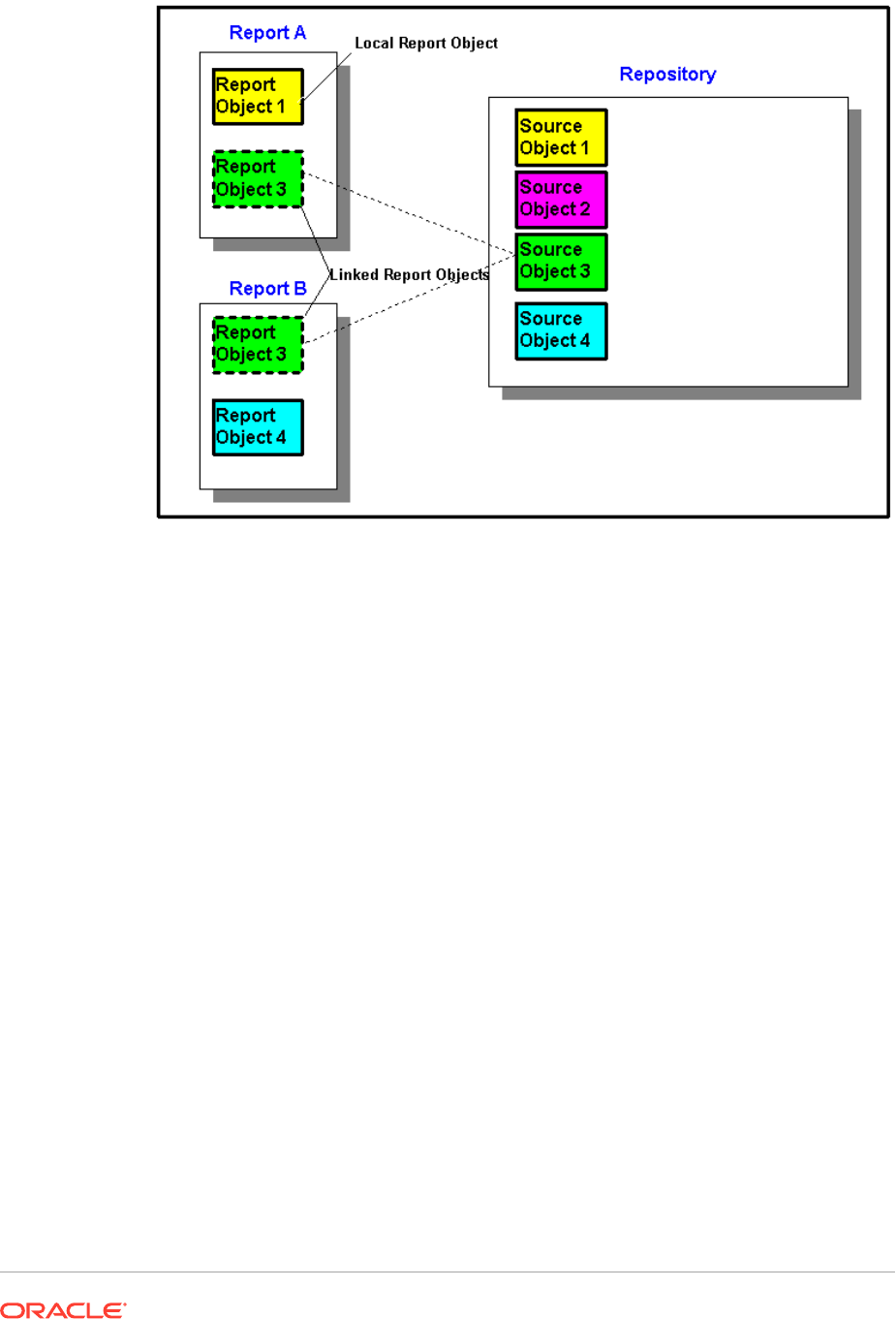
Figure 1 Linked and Local Report Objects
In Report A, Report Object 1 is copied from the repository as a local object. Changes
made to the local report object are not reflected in the source object. Report Object 3
is linked to its source object in the repository. Changes made to Report Object 3, when
saved, are reflected in the source object and other reports that are linked to that
source object, including Report Object 3 in Report B.
Defining the User Point of View
Use Financial Reporting Web Studio to set up and change the user POV.
Related Topics
• About the User Point of View
• Setting Up the User Point of View
• Changing the User Point of View
About the User Point of View
Every data value in a report is derived from the intersection of a member from each
dimension in an Planning database connection. In Financial Reporting Web Studio,
you can place these dimensions on the report grid or in the user point of view. When
you view the report, you can change the member selected for dimensions on the user
point of view. This allows you to customize a report to fit your needs. You can also use
the user point of view in books.
In a report, the member specified for a dimension in the user point of view is used for
all grids with that dimension. For example, if you select the "budget" member for the
"scenario" dimension, all grids in the report with "scenario" in the user point of view use
"budget " when you retrieve data. The user point of view is not displayed if all of the
dimensions are placed on the grid.
The following dimensions are displayed on the user point of view bar:
• Dimensions not currently defined in a row, column, or page
• Dimensions in a row, column, or page that are flagged for the current point of view
• Dimensions without a member selected on a grid point of view
• Attribute dimensions dragged to the point of view area in the Dimension Layout dialog
box
Setting Up the User Point of View
When you design a report, you limit the members on the user point of view for a database
connection. The user point of view applies to all grids that use that database connection.
To set up the user point of view:
1. With a grid selected, select Task, and then Set Up User POV.
2. In the Setup User POV dialog box:
• For each dimension, define whether the user point of view will include all members in
the dimension, or an individual member.
The default is to include all members for each dimension. To define an individual
member for a dimension, click
, and then select a member from the Select
Members dialog box. If you have an individual member selected and wish to return to
the setting to include all members, click
• Select Show Dimension Name to show the dimension name in the user point of
view.
• Select Show Member Name to show the member name in the user point of view.
• Select Show Alias to show alias names in the user point of view. If you select Show
Alias, select an option for how to display the alias.
3. Click OK to save the information for the user point of view.
Changing the User Point of View
To change the user point of view:
1. Open a report, and then click one of the POV buttons at the top of the report layout.
2. In the Select Members dialog box, select a dimension from the Dimension drop down,
then select the member for that dimension, and then click Update.
3. Optional. Select another dimension and assign the desired member.
4. Continue assigning a member to each dimension as desired.
5. Click OK to close the Select Members dialog box.
Creating Headers and Footers
Use headers and footers to add a description, add graphics, or insert text functions.
The header is located immediately below the top margin, and the footer is located
immediately above the bottom margin.
To create a header or footer:
1. With a report displayed in Financial Reporting Web Studio, in Report, in the
Header or Footer section, click
, and then select whether to enter a Saved
Object, an Image, or Text.
2. Enter the Header Height or Footer Height in inches.
3. Customize the header or footer by entering additional properties.
Creating a Title Page
Create a title page to be displayed before your report.
1. Open a report to which you want to add a title page and add a text box in the
Header section in the Report Designer workspace.
2. Select a report object below the text box, then from that report object’s property
sheet, select Page Break Before.
3. Design the text for the title page using the options in the Text Properties sheet.
Using Text Functions to Display Information
Text functions display information such as the report name or description, information
about databases associated with grids or about data in a database connection.
You can use text functions in text boxes, data rows or columns, formula rows or
columns, or page headings. Enclose the formula in double angle brackets (<<) and
(>>) to distinguish different text functions. The font for the text function can be
formatted like regular text. See Text Functions for information about text functions.
To use text functions to display information in a report:
1. With a report open in the Report Designer, do one of the following
• Select a text box, and then click
.
• Select a text cell in a grid, and then in Cell Properties, click .
• Select a heading cell in a grid, and then in Heading Column Properties or
Heading Row Properties, select Custom Heading and click .
2. In the Insert Function dialog box, select a function, and then click OK.

Note:
You can enable or disable error messages for text functions that are displayed in
the grid or text object. The default is to display error messages. To disable this
feature, from Text Properties, clear Show Text Function Errors.
Note:
You must format the entire text function, including the angle brackets, with the same
font properties.
Searching for Information in the Repository
You can search for information in the Financial Reporting repository.
1. Open Financial Reporting Web Studio.
2. In the Repository section, enter a text string to search for, and then click .
Tip:
To clear the results of the search, click
.
Filtering Repository Items
You can filter the items that are displayed in the repository.
1. In the Repository pane, click the drop-down button .
2. Select which item or items to display:
• All
• Reports
• Snapshot Reports
• Grid
• Chart
• Text
• Image
• Row/Column Template
3. Click .
Note:
If the list of repository items is filtered, the search button turns blue indicating
that the repository listing is filtered . Once all filters are removed and a
search is performed, the icon turns grey indicating that there are no filters
applied to the current repository listing .
Viewing Hidden Artifacts
Sometimes artifacts are hidden from users in the repository by the report designer; for
example, target reports for related content.
When an artifact is hidden, Hidden Item is selected in the Advanced Properties in
the Explore repository. By default, hidden artifacts are not displayed in Financial
Reporting Web Studio.
If you need to edit an artifact that is hidden, you can "unhide" it in Financial Reporting
Web Studio by doing the following:
1. Open Financial Reporting Web Studio.
2. Select View, and then Show Hidden Artifacts.
The hidden artifacts will be displayed on the left side of the Financial Reporting
Web Studio repository panel.
Viewing Report Summaries
A report summary shows the name, the description, and the creator of a report.
In addition, a report summary shows the modifier, date, and time the report was last
modified. Summary information is saved when you save the report.
Report summary information is displayed under repository information.
Viewing Report Server Information
View report server information to monitor the activity on your server.
Report server information is displayed in the Summary Panel below the repository.
Working With Grids
Related Topics
• About Grids
Grids are tables that can contain data from external database connections.
• Adding a New Grid
When you create a report, you must add a grid.

• Inserting an Existing Grid
You can insert an existing grid into a report.
• Selecting a Grid
To select a grid in the Report Designer, click the top left cell to select the rows and
columns inside the grid.
• Defining the Grid Point of View
The grid point of view (POV) is the user point of view at the grid level.
• Working With Rows and Columns in Grids
Insert rows and columns; change the height and width; define headings; insert page
breaks; define formulas; add auto calculations; apply formatting; and use templates.
• Formatting Grids
Format numbers, apply currency formats, align and replace text, hide and sort rows and
columns, modify the font, create custom colors, add borders and shading.
• Using the Formula Bar
The formula bar provides a central location to create formulas and select members when
setting up grids in Financial Reporting Web Studio.
• Assigning Multiple Database Connections to a Grid
Retrieve data from different database connections and define the database connection
for each data row or data column.
• Setting Data Query Optimization Options
When working with grids, you can set data query optimization options to optimize the
efficiency of your data queries.
• Showing Supporting Detail for Planning
When you use a Planning database connection and select a row, you can display
supporting detail for a member.
• Saving a Grid
When you save a grid, you can create a link between the grid and the source object in
the repository.
• Exporting a Grid Design to Excel
You can export a report's grid design information as it appears while viewing the grid in
Financial Reporting Web Studio to Excel.
About Grids
Grids are tables that can contain data from external database connections.
You can add a grid to your report, define its dimension layout, select members, and then
format the grid. You can also insert an existing grid to reuse a pre-formatted grid design. You
can use text, dimensions, members, and formulas to define the grid content. You can also
hide a grid. For example, you might want to display a chart in a report, but not the grid
associated with the chart.
Note:
In Microsoft Excel, reports containing two grids that are side by side do not display
the grids side by side; instead, the grids are displayed one above the other.

Adding a New Grid
When you create a report, you must add a grid.
To add a new grid:
1. Do one of the following:
• Click
, and then position the grid in the Body section in the Report
Designer.
• Select Insert, then Grid, and then position the grid in the Body section in the
Report Designer.
• In the Body section in the Report Designer, click , and then select Grid.
2. In Database Connection Properties, select an existing database connection, or
click New Connection to create a new database connection.
3. In Dimension Layout, drag dimensions from Attribute Dimension (if they exist)
and from Point of View, into Page, Rows, and Columns, and then click OK.
You can place multiple dimensions into Page, Rows, and Columns. The
dimensions that are not placed in Pages, Rows, or Columns are displayed in the
user point of view bar located at the top of the Report Designer for the grid.
You can layer multiple dimensions in a row, column, or page. For example, you
might want to place the Scenario and Time dimensions on the same axis to show
actual and budget data over a period of time.
When you add a new grid, the system assigns a default name to the grid. The default
name assigned is Gridn, where n is a system-assigned identification number. For
example, if you save a grid that is the sixth system-named grid saved in the report, the
default name is Grid6. You can rename the grid in Grid Properties.
The system uses the grid name when a function or chart references the grid. For
example, if you design a chart to graphically display the data from a grid, the chart
properties must reference the grid by its name.
Inserting an Existing Grid
You can insert an existing grid into a report.
1. In the Body section in the Report Designer, do one of the following:.
• Select Insert, and then Saved Object.
• Right-click and select Insert Object, and then Saved Object.
• Click
, and then select Saved Object.
2. In Type, select Grid.
3. Select the desired grid object, and the click Insert.
• To use the grid object as a linked object, select Link to Source Object.
• To use the grid object as an unlinked object, clear Link to Source Object.

Note:
If only linked grids are inserted into a report, the report will not be displayed in
the Reports section in the Simplified Interface. Insert a new single cell hidden
grid in the report in order for the report to be displayed.
Selecting a Grid
To select a grid in the Report Designer, click the top left cell to select the rows and columns
inside the grid.
When you select a grid, you can right-click to access the following options:
• Dimension Layout—Change the dimensions for the pages, rows, and columns.
• Grid Point of View—Display or hide the Grid Point of View bar.
• Grid Point of View Setup—Select members for the Grid Point of View.
• Data Query Optimization Settings—Suppress the rows on the database connection
server or the report server. (See Setting Data Query Optimization Options.)
Defining the Grid Point of View
The grid point of view (POV) is the user point of view at the grid level.
Related Topics
• About the Grid Point of View
• Setting Up a Grid Point of View
• Showing or Hiding the Grid Point of View
• Selecting Members for the Grid Point of View
About the Grid Point of View
The grid point of view (POV) is the user point of view at the grid level. The grid POV enables
you to specify the members for a dimension in a grid without placing the dimension on the
row, column, or page intersection. This allows you to control or limit the selection of members
available to users who view or print the report. Setting the grid POV prevents prompting for
the user POV each time the report runs. After you specify a dimension in the grid POV, you
can determine how viewers select members.
By default, the grid POV is set to use whatever dimensions are in the user POV. If one or
more dimensions are needed to have a selection different than the user POV, you can select
the dimension(s) for the grid POV, and the report will use the grid POV instead of the user
POV.
Tip:
To improve report performance, do not use dimensions with only one
member selected for the entire grid in a row, column, or page axis. Although
it does not increase the potential cell count, it adds overhead to the entire
query. Dimensions that are substitution variables or set to one member
should be left in the POV. For point of view dimensions where the member
can be changed by the end user, use the user POV. For point of view
dimensions where the member will remain fixed at a specific selection, use
the grid POV.
Setting Up a Grid Point of View
To set up a grid point of view:
1. In the Report Designer, select the top left cell of the grid to select the entire grid.
2. Do one of the following:.
• Right-click the grid, and then select Grid Point of View Setup.
• In Grid Properties, click
.
3. In the Setup Grid POV dialog box:
• For each dimension, define whether the grid point of view will include all
members in the dimension or an individual member.
The default is to include all members for each dimension. To define an
individual member for a dimension, click , and then select a member
from the Select Members dialog box. If you have an individual member
selected and wish to return to the setting to include all members, click
• Select Show Dimension Name to show the dimension name in the grid point
of view.
• Select Show Member Name to show the member name in the grid point of
view.
• Select Show Alias to show alias names in the grid point of view. If you select
Show Alias, select an option for how to display the alias.
4. Click OK to save the information for the grid point of view.
Showing or Hiding the Grid Point of View
As you design your reports, you can hide or display the grid point of view. Hiding the
grid point of view prohibits you from changing the grid point of view when viewing a
report. By default, the grid point of view is hidden. However, even when the grid point
of view is hidden, its values are still operative when running the report.
To show or hide the grid point of view, do one of the following:
• Select the grid, and then in Grid Properties, select or clear Grid Point of View.
• Right-click the grid, and then select Grid Point of View.
Note:
The grid point of view displays only in HTML view. Since the report is interactive in
HTML view, you can change the grid point of view members. Since PDF documents
are static documents, you cannot change the grid point of view in PDF documents.
Selecting Members for the Grid Point of View
On the grid POV bar, you can select members for dimensions that are not used in rows,
columns, or the page axis. The members defined on the POV bar complete the criteria used
to retrieve data for the grid. Each POV dimension can contain only one member.
Note:
Using dimensions with security on the grid point of view may cause unexpected
results.
To select a member for the grid point of view
1. Display the grid point of view bar.
• Select the grid, and then in Grid Properties, select Grid Point of View.
• Right-click the grid, and then select Grid Point of View.
2. On the grid point of view, click a dimension to display the Select Members dialog box.
3. In the Select Members dialog box, select a member for each dimension, and then click
OK.
Working With Rows and Columns in Grids
Insert rows and columns; change the height and width; define headings; insert page breaks;
define formulas; add auto calculations; apply formatting; and use templates.
Related Topics
• Inserting Rows and Columns
• Changing the Row Height and Column Width
• Defining Row and Column Headings
• Overriding a Row or Column Heading
• Cutting, Copying, and Pasting Rows and Columns
• Inserting Page Breaks Before a Row or Column
• Defining Formula Rows and Columns
• Adding Auto Calculations to Data Rows and Columns
• Applying Formatting to Auto Calculated Data Rows and Columns

• Using Row and Column Templates
Inserting Rows and Columns
You insert rows or columns into a grid to add data to the grid. Types of rows and
columns include:
• Data—Members of dimensions that are retrieved from a database connection. The
member in a data row or column defaults to the top-level member of the
dimension.
A # symbol indicates data rows, columns, or cells.
• Formula—Values based on formulas. Commonly used to calculate totals,
averages, and variances on data rows or columns.
An = # symbol indicates formula rows, columns, or cells.
• Text—Text typed into the cells or added dynamically through a text function.
Text rows, columns, or cells in grids do not contain symbols when added to a grid.
They are initially blank until populated with text.
When you add a grid to a report, it contains one of each of the following:
• Data row
• Anchor row
• Data column
• Anchor column
An anchor row or column is a blank row or column located at the end of the rows or
columns. You can add one or more rows or columns in a grid, or you can use the
anchor row and column to append new rows and columns.
To insert a row or a column in a grid:
1. In an existing grid, select a cell, row, or column.
2. Select Insert, then Row or Column, and then Data, Formula, or Text.
To insert multiple rows or columns, select the number of rows or columns on the
grid equal to the number of rows or columns that you want to insert.
3. Populate the row or column:
• For a data row or column, double-click the row or column heading and select
dimension members to place in the row or column. See Assigning Members to
Data Rows or Columns.
• For a formula row or column, select the row or column heading and build a
formula in the formula bar at the top of the Report Designer.
• For a text row or column, enter text directly in the row or column, in the
formula bar at the top of the Report Designer, or in Text Properties. See
Formatting Text Objects.
Note: Text in a text cell, that extends beyond the width of the cell, does not extend to
fill the adjacent cells when rendering the report output. The text content will wrap in the
single cell. When creating long text that does not fit in a single grid cell, use a text box
below the grid instead.
Changing the Row Height and Column Width
You can change row heights and column widths in grids. You can apply these changes to the
entire grid or to specific rows or columns.
To change row height and column width:
1. In an existing grid, select row or column.
2. In Row Properties, enter a Row Height.
Select Adjust Row Height to Fit to increase the height of the row to fit all the contents of
the cells in that row. (Applicable to PDF Preview)
3. In Column Properties, enter a Column Width.
Select Adjust Column Width to Fit to increase the width of the column to fit all the
contents of the cells in that column. (Applicable to PDF Preview)
Note:
The row height and column width of report objects is specified in measurements of
1440 units per inch. The row height and column width of grid objects is specified in
measurements of 96 units per inch.
Tip:
You can drag the handle of a row or column in the grid to the desired size. If you
make a row or column too small to see, when the pointer becomes a split line, drag
the row or column handle until the row or column is visible.
Defining Row and Column Headings
To define row and column headings for a grid:
1. In an existing grid, select the cell in the upper left corner of the grid.
2. In Grid Properties, under the Headings section, define the following information about
the heading:
• In Member Labels, select what to display in the heading (Member Name, Alias, or
Both).
• In Row Headings Before, select a column.
The row heading is positioned to the left of the selected column. Columns are
represented alphabetically as Column A, Column B, Column C, and so on. You
cannot place row headings before columns that are sorted.
• Select Suppress Repeats to hide headings for repeating members in a segment.
When you suppress repeats, only the first instance of the heading for a repeated
member is displayed. Headings for additional repeating members are hidden.
• In Alias Table, select the alias table to use when showing aliases.
You can select alias tables in your database connection. Although you cannot
specify aliases at the grid level, if you display aliases for a row or column, the
system displays the alias table as selected at the grid level. The alias table is
initially set to the default alias table for the database connection type.
Note:
The heading properties you define apply to all rows and columns unless you
specify otherwise.
Overriding a Row or Column Heading
To override a specific row or column heading in the grid:
1. Select a row or column heading in the grid.
2. In Heading Row Properties or Heading Column Properties, select Custom
Heading, and then either:
• Enter the text to use for the heading.
• Enter a text function, or click
and select the text function you want to use
for displaying data on the headings.
3. Optional: Select Allow Expansion to enable expansion of the summary rows and
columns under the heading.
Note:
If a Custom Heading is specified for a member where Allow Expansion is
enabled, the custom header specified will be applied to all descendants of
the expanded member.
Cutting, Copying, and Pasting Rows and Columns
When cutting or copying rows and columns, keep in mind the following points:
• You can copy rows and columns and paste them in the same grid or between two
different grids in a report.
• If you cut a row or column, you can only paste it in the same gird.
• For formula rows and columns, you must copy or cut the entire row or column.
To cut, copy, and paste rows or columns in grids, select the desired rows or columns,
and then right-click and select Cut, Copy, or Paste.

Inserting Page Breaks Before a Row or Column
Inserting a page break before a row or column in a grid enables you to break the report data
at a specified location while keeping required line items together. Page breaks are indicated
with a heavy, dashed line.
To insert a page break before a row or column in a grid:
1. With a grid displayed in the Report Designer, select a row or column.
You cannot insert a page break before the first column in a report or above the first row in
a report.
2. In Row Properties or Column Properties, select Page Break Before, and the select
where to position the page break:
• For rows, select Position at Top to place the remaining part of the grid at the top of
the new page. For columns, select Position at Left to place the remaining part of the
grid in the left margin of the new page.
• Select Same Position to place the grid in the same position as it is currently placed.
For example, if a grid is placed half way down the page and you insert a page break
with Same Position selected, the remaining part of the grid will be displayed half way
down the second page.
Defining Formula Rows and Columns
A formula consists of a combination of grid references, mathematical functions, and
arithmetic operators. A grid reference uses values from the current grid or another grid in a
calculation. You can define arithmetic formulas on formula rows, columns, cells, or a range of
formula cells in a grid. For example, you can build a formula that adds one or more rows. Or,
you can multiply two rows, add a third row, then display the result. For a explanation of the
mathematical functions you can use in formulas, see Mathematical Functions.
When defining formula rows or columns, keep in mind the following points:
• Formula results are calculated based on the underlying data values in one or more
specified cells. If the cells used in a formula are formatted to use scaling, the formula
results may differ from the displayed values for the cells, since the underlying,
unformatted data values are used in the formula.
• By default, cells that contain missing data (
#MISSING
) are not treated as zero (0) in
formulas, unless specified differently using the "IfNonNumber" property. In a formula that
uses division, an error is returned.
• Use do notation to specify mathematical properties. Dot notation is a syntax that specifies
properties for a grid or another property. Specify the property using a period ( . ) followed
by the property name.
Formula Row and Column Syntax
Syntax:
gridname.row\column[x].property

Argument Description
gridname Name of the grid. Grid names cannot include spaces. When specifying
the full
gridname
notation, you must also indicate the row, column, or
cell.
x Row or column, number, and property.
Example 1
Add all elements in row 3 of
mygrid1
.
mygrid1.row[3].sum
Example 2
Return the sum of the nth column:
mygrid2.column[C].sum
Example 3
Returns the absolute value of the cell located at the intersection of row 5 and column B
in the current grid:
ABS([5,B])
Inserting a Formula Row or Column
To insert a formula row or column:
1. In an existing grid, select Insert, then Row or Column, and then Formula.
The formula row or columns is inserted with a = # symbol.
2. In the formula bar at the top of the Report Designer, select a function from the
drop-down list, and then enter the formula in the formula text box to the right of the
drop-down.
See Using the Formula Bar.
Showing the Formula In a Row or Column Heading
To show the formula in the heading for formula row or column:
1. In a grid, select the heading cell.
2. From Heading Row Properties or Heading Column Properties, select Show
Formula.
Calculating at the Cell Level
You can create a custom cell-level formula on cells in a formula row or column. When
you select a formula cell, you can select the following calculation preferences in Cell
Properties:
• If the cell is an intersection of a formula row and formula column, you can choose
whether the calculation is based on the row formula, the column formula, or a new
custom formula.
• If a cell is located in a formula row, you can choose whether the calculation is based on a
row formula or a new custom formula.
• If a cell is located in a formula column, you can choose whether the calculation is based
on a column formula or a new custom formula.
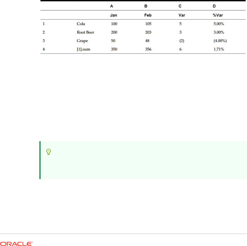
Figure 1 shows an example of a cell that is calculated to display the % variance. Cell D4
displays the % variance between the sum of "Jan" and the sum of "Feb"; specifically,
((356-350)/350) *100=1.71%
. A cell level formula gives the intended result by placing a
custom formula in the cell D4. The formula needed to get the correct result is
(([B]-[A])/
[A])* 100
.
Figure 2 Reason for Using Cell Level Calculation
To calculate at the cell level:
1. Open a report and select a grid.
2. Select a formula cell or cells.
3. In Cell Properties, under Calculation order, select one of the following options:
• Use the row formula— Applies the row calculation to the cells.
• Use the column formula—Applies the column calculation to the cells.
• Use a custom formula— Adds a new formula. (Enter the custom formula in the
formula bar at the top of the Report Designer.)
Tip:
You can select multiple contiguous formula cells in a formula row or column to
change the calculation order.
Expanding Rows and Columns
You can use the design-time row, column, and cell to reference the calculated rows, columns,
or cells.
Row or Column Syntax:
AXIS[Segment(Range)].Property
Cell Syntax:
CELL[Row Segment(Range), Column Segment(Range)].Property
Parameters:
Parameter Description
AXIS
Row or column containing the expanded cells identified by the row and column
templates.
For example, [3] refers to row 3 and [C] refers to column C. For example,
[3].sum
in a column formula is calculated as the sum of row 3.
The default is row.
CELL
Intersection of the expanded cells, given the row and column template
coordinates, respectively.
For example,
[2,C]
is the single cell where row 2 intersects column C.
Segment
Value that represents a row or column ID in the Report Designer.
Referenced segments refer to design-time rows or columns, which can expand in
the viewer. View-time rows and columns are the expanded rows and columns.
Use numbers for row IDs and letters for column IDs.
Note:
If you are using an expanded formula row, the
default segment is row. If you are using an
expanded formula column, the default segment is
column. For example, row [ 5 ] refers to expanded
row 5. For more information on segments, see
Expressing the Segment Argument.
Range
Expanded cells used in the calculation of the function.
Range refers to view-time expanded rows and columns. Calculations are
performed after suppression. Sorting is performed after calculations. For more
information on sorting and suppression, see Using Conditional Suppression and
Sorting Rows, Columns, or Pages in Grids.
Use colons to refer to a range of expanded rows or columns. For example,
(3:6)
addresses rows 3, 4, 5, and 6. For more information on ranges, see Expressing
the Range Argument.
Property
Function applied to aggregate rows, columns, or cells. For more information on
using properties, See Aggregate Property Arguments.

Expressing the Segment Argument
The Segment argument is a value that represents a row or column ID in the designer.
Referenced segments refer to design-time rows or columns, which might expand in the
viewer. View-time rows and columns are the expanded rows and columns. You can use
numbers for row IDs and letters for column IDs. You can refer to one or more segments in
any standard formula..

Table 1 Notation Used for Multiple Segments in Standard Formulas
Type Notation Description Example
Single segment [ ] Single (design-time)
segment
Point to segment 2:
row[2]
N
o
t
e
:
P
r
e
v
i
o
u
s
r
e
l
e
a
s
e
s
s
u
p
p
o
r
t
t
h
i
s
n
o
t
a
t
i
o
n
.
Table 1 (Cont.) Notation Used for Multiple Segments in Standard Formulas
Type Notation Description Example
Nonconsecutive segment [;] Multiple single rows or
column segments
Point to segment rows 2, 5,
7, 8 and 10:
row[2;5;7;8;10]
N
o
t
e
:
U
s
e
a
s
e
m
i
c
o
l
o
n
r
a
t
h
e
r
t
h
a
n
a
c
o
m
m
a
t
o
d
e
l
i
n
e
a
t

Table 1 (Cont.) Notation Used for Multiple Segments in Standard Formulas
Type Notation Description Example
e
r
o
w
o
r
c
o
l
u
m
n
r
e
f
e
r
e
n
c
e
s
.
Segment Range [:] Range of rows or column
segments
Point to segment rows 2, 3,
4 and 5:
row[2:5]
The following examples show different combinations of the segment notation in Table
1.
Example 1:
Point to segment rows 1, 3, 5, 6, 7, 8, 9, 10, 12, 13, 14, 15 and 17:
row[1; 3; 5:10; 12:15; 17]
Example 2:
If the following expression references row segment 20, but the grid contains only 15
row segments, the formula works only on segment 4:
row[4; 20]
If you enter a larger starting segment than ending segment, the system internally
switches them around.

Example 3:
Show how the segments are internally switched:
row[6:3] becomes row[3:6]
Multiple references to the same segments are valid. This causes the same segments to be
included twice in an expression.
Example 4:
Sum row 5 twice:
row[2;3;5;7;5].sum
Example 5:
Reference row segments 2, 3, 4, 5, 6, 7, and segment 5 again. Include segment 5 twice in
the calculation of the average:
row[2:7;5].avg
Text segments are ignored.
Example 6:
Ignore row segment 3 if it is a text row:
row[1:5]
Expressing the Range Argument
The Range argument refers to view-time expanded rows and columns, on which calculations
are performed after suppression. Sorting is performed after calculation is completed.
Table 2 Range Notation
Type Notation Description Example
None The Range argument is
optional.
Point to all expanded
rows in row segment 2.
row[2]
Single Range [segment (range)] Single expanded row or
column
Point to expanded row 5
in segment 2:
row[2(5)]
Consecutive Range
Reference
[:] Range of expanded
rows or columns
Point to expanded rows
5,6,7,8,9,10 in row
segment 2:
row[2(5:10)]

Table 2 (Cont.) Range Notation
Type Notation Description Example
Nonconsecutive Range
references
[,] Multiple single
expanded rows or
columns
Point to expanded rows
5, 7, 8 and 10 in row
segment 2:
row[2(5,7,8,10)]
If a range is used, you can use any combination of the range notations in Table 1.
Example 1:
Point to expanded rows 5 through 10 in design-time row 2:
row[2(5:10)]
If row segment 2 expands to 15 rows, the function operates on only expanded rows 5
through 10.
Example 2:
Identify columns C through E in design-time column A:
column[A(C:E)]
Example 3:
Point to expanded rows 1, 3, 5, 6, 7, 8, 9, 10, 12, 13, 14, 15 and 17 in design-time row
2:
row[2(1,3, 5:10, 12:15, 17)]
When the grid contains suppression properties, expanded rows and columns may be
suppressed. If the Range argument refers to a number of expanded rows that is
greater than the maximum number of rows expanded in the segment, the extra rows
are ignored.
Example 4:
In the following example, expanded rows 6 through 10 are identified, but segment 1
contains only 3 expanded rows. In this situation, the function works only on expanded
rows 6 through 8:
row[1(6:10)]
If none of the expanded rows in the Range exist, the entire axis reference is ignored.
Example 5:
Ignore the reference to 23 if segment 3 only contains 10 expanded rows:
row[3(23)]

Example 6:
If you enter a larger starting range than ending range, the system internally switches them
around. The following shows how the range is reversed:
row[1(7:5)] becomes row[1(5:7)]
Multiple references to the same expanded rows or columns are valid. However, this may
cause the same rows or columns to be included twice in an expression.
Example 7:
Sum expanded row 5 twice:
row[2(3,5,7,5)].sum
Example 8:
Specify expanded rows 3, 4, 5, 6, 7, and row 5. Include row 5 twice in the calculation of the
average:
row[2(3:7,5)].ave
Identifying Multiple Segments with Ranges
The syntax for a range in a segment range is:
AXIS[Segment Start : Segment End (Range Start : Range End)]
where
Segment Start
and
Segment End
refer to multiple segments.
Example 1:
Point to expanded rows 5, 6, and 7 in row segments 1, 2, 3, and 4:
row[1:4(5:7)]
Example 2:
Point to expanded rows 5, 7, and 9 in row segments 1, 2, 3, and 4:
row[1:4(5,7,9)]
If the segment argument refers to segments that do not exist in the axis, the segments are
ignored. This includes suppressed rows or columns.
Example 3:
Point to expanded rows 4, 6, 7,8, 9, and 10 in row segment 1 and 4, 5, and 6 in row segment
3 and all expanded rows in row segment 7:
row[1(4, 6:10); 3(4:6); 7]

Adding Auto Calculations to Data Rows and Columns
Related Topics
• About Auto Calculations
• Considerations When Adding Auto Calculations
• Adding an Auto Calculation
About Auto Calculations
You can append auto calculations to the data rows and columns in a grid. For
example, you could calculate the total rows or columns that expand and contain
multiple dimensions.
When you define an auto calculation for a data row or column, a row or column that
contains the calculated value is inserted at runtime. The calculation applies to all
members in a row or column and is displayed when you print or preview the report.
You can apply several formatting options. For each auto calculation, you can specify a
heading for the calculated row or column and a group heading. You can specify the
location of the calculation row or column in relation to the member, and you can insert
blank rows before and after calculation rows and group headings. You can also specify
page breaks within rows of calculation and after a calculation row.
You can apply several of the formatting options provided with auto calculation but
exclude the auto calculation function for a specified cell, row, or column.
You can define different types of calculation for each dimension or member in the row
or column using one of the following functions:
• Average—Average value of values in the segment in the dimension at runtime
(ignores non-number values)
• Average All—Average value of values in the segment in the dimension at runtime
(assigns 0 to non-number values)
• Count—Number of values in the segment in the dimension at runtime (ignores
non-number values)
• Count All—Number of values in the segment in the dimension at runtime (assigns
0 to non-number values)
• Maximum—Largest value of the values in the segment in the dimension at
runtime
• Minimum—Smallest value of the values in the segment in the dimension at
runtime
• Product—Multiplies all numbers or references in the segment in the dimension
and returns the product at runtime
• Total—Sum of the values in the segment in the dimension at runtime
• No Calculation—A calculation is not performed on the selected cell, row, or
column; however, the formatting provided with auto calculation is retained. You can
apply No Calculation to an auto calculation row, column, or cell or non-calculation
row, column, or cell.
Considerations When Adding Auto Calculations
• If errors or missing data exist for members, the previous operations include the member
value in the subtotal, but the member value is treated as a zero value.
• You can use the formatting options without having the calculation done. This enables you
to retain the member grouping without calculations such as totals.
• Since the outermost layer of an auto calculation is the grand total of all rows in the
calculation, sorting it is not supported. Sorting on the outermost layer when auto
calculations are enabled is ignored. In addition, if you have auto calculations on more
than one layer and select Sort, you must sort on all the heading layers (except the
outermost layer) which have auto calculations.
Adding an Auto Calculation
To add auto calculations to data rows or columns:
1. In a grid, select the heading cell of a row or column that contains multiple members.
2. In Heading Row Properties or Heading Column Properties, select Auto Calculation,
and then click
.
3. In Calculation, select a function, or select No Calculation to include only auto
calculation formatting.
4. Optional: Under Headings, do the following to add headings to the calculation or group
rows or columns:
• Select Group Heading, and then enter a custom heading to describe the row or
column.
• In Auto Calculation Heading, enter a custom heading for the calculation row or
column.
To insert formulas in the heading, click See Using Text Functions to Display
Information .
Keep in mind the following:
• When using the MemberName function, you must enter "current" for the row/column/
page parameters.
• The header is suppressed if the surrounding data is suppressed.
• To suppress repeats on multiline headers, select Grid Properties, then General, and
then Suppress Repeats.
5. Optional: Under Insert Blank Row / Column, select an option to insert blank rows or
columns before or after calculation rows or columns and group headings.
6. Select a Row Height or Column Width.
7. Select Allow Page Breaks Within to allow a page break within the rows of the auto
calculation.
When deselected, the heading cell and the row are kept together. If the row is too long to
fit on a page, the heading cell and the row is moved to the next page. If the auto
calculation row is longer than one page, the option defaults to Allow Page Break Within.
8. Select Allow Page Breaks After Auto Calculation to allow a page break after the
calculation row.
9. Click OK.
10. Select the grid. In Grid Properties, expand Position, and then in Position of
Auto Calculations, select Before Members or After Members to define whether
to insert the auto calculation row or column before or after the expanded members
of the row or column.
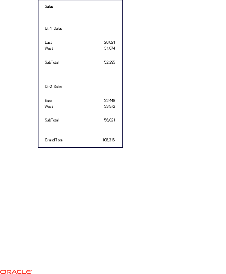
Figure 3 Example Report with Auto Calculation
Applying Formatting to Auto Calculated Data Rows and Columns
You can use the conditional formatting feature to apply additional formatting such as
underline, bold, and indent to the auto calculation rows and columns. Conditional
formatting contains two conditions specifically designed for auto calculations:
• Auto Calculation—Applies formatting to the auto calculated cells and auto
calculation heading.
• Auto Calculation Group Heading—Applies formatting to the section headings.
For more information on conditional formatting, see Applying Conditional Formatting.
To apply formatting to calculated data rows and columns:
1. In a grid, select a cell or group of cells that is set up with an auto calculation.
2. Select Format, and then Conditional Format.
3. From the Property drop-down list located below Condition 1: If, select Auto
Calculation or Auto Calculation Group Heading, and then enter the conditions.
4. Click to apply formatting to the calculated cell, and then click OK
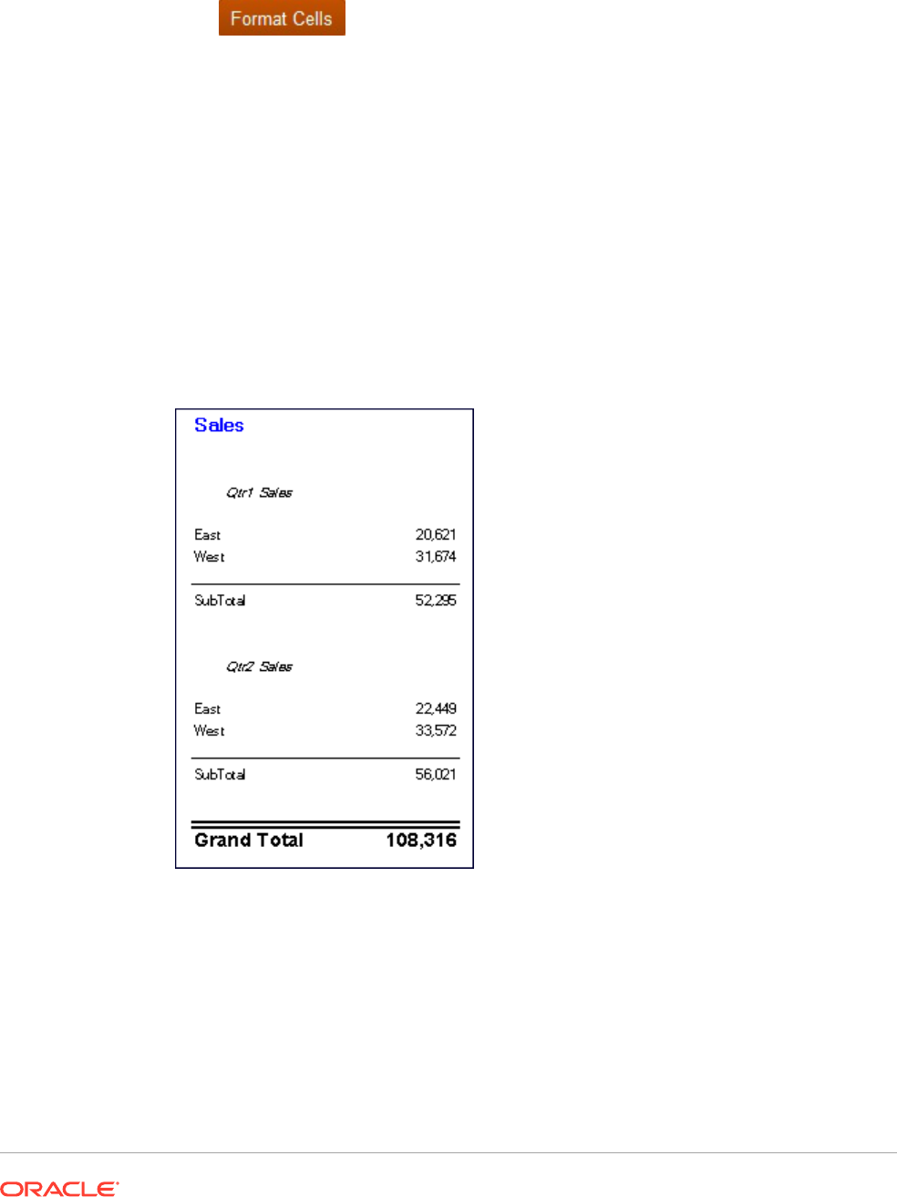
Figure 1 is an example report that uses conditional formatting to specify font, alignment, and
border and shading settings. The following conditions were applied to the example report by
selecting the East, West Heading Cell and Calculated Data Cell:
• Format 1: IF (Auto Calculation Year is True, then Format Cells (double border top, Font =
Arial, Bold, Font size = 12)
• Format 2: IF (Auto Calculation Market is True, then Format Cells (single border top)
• Format 3: IF (Auto Calculation Group Heading Market is True, then Format Cells
(Alignment = center, Font Style = italic)
• Format 4: IF (Auto Calculation Group Heading Year is True, then Format Cells (Bold,
Font size = 12, Color = blue)
Figure 4 Print Preview of Example Report with Applied Conditional Formatting
Using Row and Column Templates
Related Topics
• About Row and Column Templates
• Inheritance In Row and Column Templates
• Property Values In Row and Column Templates
• Creating a Row and Column Template

• Inserting a Row and Column Template
• Unlinking a Row and Column Template
• Modifying a Row and Column Template
About Row and Column Templates
Using row and column templates, you can select a contiguous set of rows or columns
and save them as an object in the repository to reuse in reports. Row and column
templates include one or more row or column definitions. These row or column
definitions may contain:
• Database connection/dimension/member selections
• Formula rows and columns
• Expansions
• Headings, including customized formatting
• Text rows and columns, where only the text in the heading cells is saved
• Cell formatting
• Basic suppression (#Missing, #Zero, #Error)
When you create a row and column template, the following items are discarded:
• Cell formulas
• Secondary database connection specifications
• Text from the data cell area (text in the heading cells is retained)
• Conditional formatting
• Related content
• Conditional suppression
After you create a row and column template, you can save it to the repository with the
following limitations:
• Formulas must refer to rows and columns within the selected rows or columns in
the template.
• Formulas outside the row and column template cannot refer to selected rows and
columns that are part of a row and column template.
Note:
When a report contains two or more templates and one of the templates
cannot be retrieved because it is moved, renamed, deleted from the
repository, or the data source for the template has changed, the link to
the existing template remains unbroken. No alerts for broken links are
given; however, you can check for orphan links in the
FRLogging.log
file.

Inheritance In Row and Column Templates
When inheritance is used with linked row and column templates, certain formatting options
are dynamic and vary from report to report. When a linked row or column template is used in
a grid, the format inheritance is automatically reset to the first available non-template row
above the row template or to the left of the column template
To keep the format of a row/column template consistent, or if you are experiencing formatting
inconsistencies with inheritance and row or column templates, you can do one of the
following:
• Insert a hidden text row or column containing the formatting to show in the row or column
template and set the Inherit from on the Property sheet to reference the hidden row or
column.
• Do not use inheritance, but rather set the row or column template with formats through
the Format dialog box.
Note:
Cell format inheritance must be set before creating the row and column template.
When inheriting formatting in a row and column template, you must use the Inherit
Formatting from option on the Row and Column Template property sheet, which
indicates the options that are available for inheritance. For example, suppression,
formatting, and row height or column width.
Property Values In Row and Column Templates
Related Topics
• Saved Or Inherited Property Values
• Discarded Property Values
Saved Or Inherited Property Values
Table 3 Saved or Inherited Property Values (User option)
Property Value Description
Row and Column Template
database connection
Saved by row or column
Heading—Suppress Repeats Saved by row or column
Display Line Item Details Saved by row or column
Headings Saved by row or column
Allow Expansions Saved by row or column
Calculations Saved by row or column
Hide Always Saved by row or column
Positive Number Formatting Saved by row or column
Negative Number Formatting Saved by row or column
Decimal Places Saved by row or column

Table 3 (Cont.) Saved or Inherited Property Values (User option)
Property Value Description
Scale Value Saved by row or column
Top Border Saved by row or column
Right Border Saved by row or column
Bottom Border Saved by row or column
Left Border Saved by row or column
Shading Saved by row or column
Horizontal Alignment Saved by row or column
Vertical Alignment Saved by row or column
Indent Saved by row or column
Font Saved by row or column
Font Style Saved by row or column
Font Size Saved by row or column
Font Effects Saved by row or column
Replace Value Saved by row or column
Row Height/Column Width Saved by row or column or inherited from another row or column
and applied to all rows or columns in the row and column template
Suppression Saved by row or column or inherited from another row or column
and applied to all rows or columns in the row and column template
Page Break Before Saved by row or column discarded
Discarded Property Values
Table 4 Discarded Property Values
Property Value Description
Text from text cells Discarded—text in the heading cells is retained
Cell Formulas Discarded
Investigation Discarded
Conditional Formatting Discarded
Text in non-heading cells Discarded
Calculation Order Discarded; irrelevant outside of a grid
Secondary database
connection
Error
External References in
Formulas (text or numeric)
Error
Creating a Row and Column Template
You create row and column templates based on rows and columns in a grid. When
considering rows and columns for inclusion in a template, select those rows and
columns that contain the member selections, formulas, and formatting suitable for
future use. You can then import the row and column template to use in other grids.
When you create a row and column template, keep in mind the following points:
• When templates are updated, grids containing a link to the template are updated.

• Row and column templates must contain at least one data row or column. For example,
your template cannot consist solely of text and formula rows or columns
To create a row and column template and save it as an object in the repository:
1. In a grid, select the rows or columns to include in the template.
2. Right-click the selected rows or columns, and then select Save as Row and Column
Template.
3. In the Save Row and Column Template dialog box, enter the requested information.
To save the row and column template as a linked object in the current grid, select Link to
Source Object. Link to Source Object is disabled if all rows and columns in a grid are
selected for inclusion in a row and column template. In order to link to a source object,
the grid must have at least one data row that is not part of a row and column template.
4. Click Save.
The system validates the row and column template and checks for properties that are not
supported. Depending on the content of your row and column template, you may
encounter one or more of the following situations:
• If your row and column template contains formulas with external references (for
example, to cells outside of the selected row and column template), you are
prompted to modify those formulas before saving the row or column template. You
can save a row and column template that contains cell formulas, as these can be
discarded.
• If a secondary database connection was specified within the row and column
template, you are prompted to continue saving the template. If you save the template,
the secondary database connection you specified in the row and column template is
discarded. The primary database connection is then used for the row and column
template.
• If unsupported properties are found, an Information dialog box presents a list of
properties you can select to discard before saving the template. For example, if the
row and column template contains a cell formula, you can choose to save the
template without the formula or not save the template.
Inserting a Row and Column Template
After saving the row and column template to the repository as an object, you can insert it into
an unlimited number of compatible grids. When a row or column template is inserted into a
report, formulas outside of the template are adjusted accordingly. Only formulas within a grid
are updated; not external formulas, which refer to the grid with the template, from text objects
or another grid.
In a grid on a report, a row and column template is marked with yellow heading cells.
Dynamic linking is displayed on the Row and Column Template Properties property sheet.
To insert a row and column template:
1. In a grid, select a row or column adjacent to where you want to insert the row and column
template.
Row templates are inserted below the selected row. Column templates are inserted to the
left of the selected cell.
2. Right-click the selected rows or columns, and then select Insert Row and Column
Template.

3. In the Insert Row and Column Template dialog box , select the row and column
template to insert.
4. Select whether to link or unlink a row and column template to or from the
repository as an object.
• To create a link between the report and the template in the repository, select
Link to Source Object. You can link the row and column template to the
current grid so that the grid maintains a dynamic connection to the row and
column template preserved in the repository.
A template that is linked within a grid can only be modified through format
inheritance. See Inheriting Cell Formatting.
• To use the template in the report without maintaining a dynamic link to the
source object in the Explore repository, clear Link to Source Object. See
Unlinking a Row and Column Template.
5. Click Insert.
Unlinking a Row and Column Template
After inserting a row and column template in a grid, you can unlink it. This enables you
to use the row and column template as a structural template rather than a dynamically
connected replica of the row and column template in the repository.
When you unlink a row and column template, the rows and columns in the template
are converted into standard, unlinked rows and columns.
To unlink a row and column template:
1. In a grid, select the row and column template to unlink.
2. On the Row and Column Template Properties property sheet, clear the Link to
Source Object check box.
3. When an Information dialog box asks whether to unlink this object, click Yes.
Modifying a Row and Column Template
You can modify a row and column template using one of the following methods:
• Create a new row and column template and save it using the same name as a row
and column template located in the repository, overwriting the existing template
when prompted.
See Creating a Row and Column Template.
• Unlink a row and column template from a grid, then modify and save it to the
repository using the same name and folder of the row and column template in the
repository, overwriting the existing template when prompted.
See Unlinking a Row and Column Template.
Either method replaces the original row and column template in the repository.
Formatting Grids
Format numbers, apply currency formats, align and replace text, hide and sort rows
and columns, modify the font, create custom colors, add borders and shading.

Related Topics
• Formatting Numbers in Grids
• Using Special Currency Formats
• Aligning the Text in a Grid
• Replacing Text in a Grid Cell
• Hiding Rows, Columns, or Grids
• Sorting Rows, Columns, or Pages in Grids
• Modifying the Font
• Creating Custom Colors
• Adding Borders and Shading to Cells in Grids
• Freezing Grid Headers
• Hiding Grid Lines
• Inheriting Cell Formatting
• Copying Cell Formatting
• Merging Several Cells Into One Cell
Formatting Numbers in Grids
When you format how numbers are displayed in a grid, you can define the formatting options
for an entire grid or for individual cells, rows, or columns:
To format numbers in a grid:
1. In the Report Designer, select one or more cells, or select the entire grid.
2. Select Format, and then Cell.
3. In the Format Cells dialog box, in the Number tab, define the following options:
• Positive Number Symbols—Select a prefix or suffix for positive numbers.
Note: If you need more than one symbol in the prefix or suffix, you can select the first
symbol from the drop-down, but you must manually enter any additional symbols.
• Negative Number Symbols—Select a prefix or suffix for negative numbers. To
display negative values in red, select Display in Red.
You can use a prefix to reverse the sign of an account member without inserting
another row or column. When using conditional formatting, you specify an account
row and set the condition. Then, in the Negative Number Symbols prefix field, select
the negative (-) symbol. The negative (-) symbol is displayed in front of the numbers
for that row.
Note: If you need more than one symbol in the prefix or suffix, you can select the first
symbol from the drop-down, but you must manually enter any additional symbols.
• Decimal Places—Select a number from 0 to 9 to specify the number of decimal
places to apply to a number.
• Separator Characters—How to define separator characters:
– Defined by Preferences—Use the symbols specified in the user Preferences
dialog box in the Financial Reporting repository. (In the repository, select File,

then Preferences, and then Financial Reporting, and the Financial
Reporting Studio).
– Defined in Report—Define a thousands separator and a decimal
separator for the current report.
• Scale Value By—Number to multiply values by for scaling purposes.
You can enter a number, or you can select a value from the drop-down list.
The default scaling option is 1, which does not scale values. If you enter .001,
the value 2,000 is displayed as 2.
4. Click Apply, and then click OK.
Using Special Currency Formats
Some currencies use specialized formats for their currency symbols. To add a special
currency symbol to reports, the font used for that symbol must be installed on your
local machine and the server to which you connect.
To add a special currency symbol to a report:
1. Open report and select a grid.
2. Select Format, and then Cell.
3. In the Format Cell dialog box, in the Font tab, select the font for the currency
symbol.
• "AbakuTLSymSans" for the Turkish lira symbol
• "Rupee Floradian" for the Indian rupee symbol
These fonts must have previously been installed in the system where your browser
is running and on your server in order to select them.
4. Click Apply.
5. In the Number tab, in the Prefix or Suffix fields, select Rupee (India) or Lira
(Turkey) to add the symbol as a prefix or suffix for numeric values.
6. Click Apply, and then click OK.
Note:
If fonts other than "Rupee Floradian" or "AbakuTLSymSans" are used, the
country currencies are displayed with the letters "RS" and "TL" respectively.
Aligning the Text in a Grid
To align the text in a grid:
1. Open a report and select a cell or cells in a grid.
2. Select Format, and then Cells.
3. In the Format Cells dialog box, in the Alignment tab, define the following options:
• Horizontal—Horizontal alignment in the report.
• Vertical—Vertical alignment in the report.
• Indent—Number of spaces to indent the heading and the associated text, data, and
formula cells from the left margin.
• Indent Increases for Each Generation By—Amount by which the indent increases
for each generation of a member.
This option is enabled only for member rows and member selections that use
member selection functions (for example "Children(East)" or "Descendents
(Market)"). If you have an individual selection (for example "East" or "West"), you
cannot define a value.
The indentation is done on the member’s "generation", which is a number that
denotes its hierarchy position from left to right. A dimension parent is Generation 1,
and its children are Generation 2.
To indent the row headings for each generation of a selected member:
a. Confirm that you selected a row with the desired heading cell.
b. Select the number of spaces to indent the text.
This number is added to the number defined in Indent. To specify a reverse
indentation (from right to left), enter a negative number.
Select a member relationship that returns members on multiple levels; for
example: Children of ...(Inclusive), Descendants of..., Descendants of ...
(Inclusive), Parents of...(Inclusive), Ancestors of, Ancestors of...(Inclusive), and
AllMembers.
4. Click Apply, and then OK.
Replacing Text in a Grid Cell
To replace the text in a grid cell with the text in another grid cell:
1. Open a report and select a cell in a grid.
2. Select Format, and then Cell.
3. In the Format Cells dialog box, in the Inherit Formatting tab, click
next to Replace,
and select Replace Text
4. Click Apply, and then OK.
Hiding Rows, Columns, or Grids
You can hide rows, columns, or an entire grid so that the values are not displayed when you
print or view a report. For example, you might want to hide a grid if you include a chart based
on the grid data and want to display only the chart on the report.
Note:
The data and calculations in rows or columns are evaluated, regardless of the
formatting that is applied to them.
To hide a grid:
1. In the Report Designer, select a grid.
2. In Grid Properties, expand Suppression, and then select Hide Grid.
To hide a row or column in a grid:
1. In the Report Designer, select a row or a column in a grid.
2. In Row Properties or Column Properties, select Hide Always.
3. Specify whether ignore the values or calculations in the hidden row or column
when you print or view a report.
• To ignore values and calculations, select Suppression Ignores Row or
Suppression Ignores Column.
• To include values and calculations, clear Suppression Ignores Row or
Suppression Ignores Column.
Note:
Hidden cells are ignored when suppression is evaluated unless they
are specifically referenced using conditional suppression. For more
information, see About Conditional Suppression.
Sorting Rows, Columns, or Pages in Grids
You can sort a range of consecutive data rows or columns in a grid based on the
values in a specific column or row. You can also sort columns, rows, and pages based
on their headings. If you select a range of columns, Financial Reporting Web Studio
sorts the columns based on the values in a specified row. If you select a range of rows,
Financial Reporting Web Studio sorts the rows based on the values in a specified
column. If the column or row by which you sort contains multiple members, the sort is
based only on the values of the first member.
You can sort columns or rows in ascending or descending order. When you sort in
ascending order, the lowest number, the beginning of the alphabet, or the earliest date
appears first in the sorted list. When you sort in descending order, the highest number,
the end of the alphabet, or the latest date appears first in the sorted list.
You can sort only multiple ranges of columns or rows. Suppressed rows or columns
are not sorted.
Note:
When sorting on data rows or columns, text rows or columns cannot be
included as part of the sort definition.
To sort a range of rows and columns:
1. Open a report and select a grid.
2. In Grid Properties, select Sort, and then click Setup.
3. In the Sort dialog box, under Apply Sorting to the, select Rows, Columns, or Pages.
For the Pages option, you can only select headings from the Sort by: drop-down menu.
All other options are disabled.
4. For Rows or Columns, use From and To to select the range of columns or rows to sort.
When auto calculations is enabled, the outermost layers contains the grand total of all
rows in the calculation. Sorting on the outermost layer is ignored. Also, when you select
sort with auto calculation set on multiple layers, you must sort on all heading layers which
have auto calculations.
5. In Sort by, select the options by which to sort:
a. From the first drop-down list, select the headings or row or column on which to base
the sort, then select Ascending or Descending for the sort order.
b. Optional: Use the Then by drop-down lists to set up one or two additional sorts
parameters.
6. Optional: Click Add Sort to set up additional sorts:
7. Click OK.
Modifying the Font
To modify the font displayed in a grid:
1. Open a report and select a cell or cells in a grid.
2. Select Format, and then Cell.
3. In the Format Cells dialog box, select the Font tab and define the desired font.
4. Click Apply, and then OK.
Note:
You can upload additional fonts to the server. See Uploading Custom Fonts
Creating Custom Colors
Financial Reporting Web Studio provides a palette of basic colors for text in reports and other
artifacts. You can add to that palette by defining custom colors.
To define a custom color:
1. Open a report and select a cell or cells in a grid.
2. Select Format, and then Cells.
3. In the Format Cells dialog box, in the Font tab, click the arrow next to Color, and then
click Custom Color.
4. In the Select Custom Colors dialog box, define the custom color, and then click OK.

Note:
Custom colors are not saved between Financial Reporting Web Studio
sessions.
Adding Borders and Shading to Cells in Grids
You can apply borders and shading to add emphasis to selected cells, rows, or
columns in a the grids. You can specify a border style and then apply it to any sides of
the selected area. You can also select a shading color to apply shading to your
selection.
To add borders or shading to cells in a grid:
1. Open report and select the cells to format in a grid.
2. Select Format, and then Cell.
3. In Format Cells dialog box, select the Borders & Shading tab.
4. To specify a border, select a line style for the border under Style, and then click
one or more of the border placement buttons.
5. To add shading, select a color from the drop-down list under Shading.
6. Click Apply to preview your selections, and then click OK.
Freezing Grid Headers
Freezing grid headers locks the row and column headers in a report when previewed
in HTML. This setting does not lock the row and column headings in the grid editor in
Financial Reporting Web Studio.
To freeze the row and column heading in a report displayed in HTML:
1. In the Report Designer, select the top left cell of the grid to select the entire grid.
2. In Grid Properties, select Freeze Grid Headers.
Hiding Grid Lines
To hide the lines in a grid when viewing a Financial Reporting report in HTML Preview:
1. In the Report Designer, select the top left cell of the grid to select the entire grid.
2. In Grid Properties, select Hide Grid Border in HTML.
Inheriting Cell Formatting
When formatting cells in a grid, you can inherit formatting from a cell and apply it to
another cell. The following formatting options can be inherited from a cell in a grid:
• Number
• Alignment
• Font
• Borders and Shading
• Replacement Text
To inherit cell formatting:
1. Open a report and select a cell or cells in a grid.
2. Select Format, and then Cell.
3. In the Format Cells dialog box, in the Inherit Formatting tab:
• Select the formatting options to inherit.
To select all the formatting options under a category, select the check box next to the
category. For example, to inherit all number formatting options, select the check box
next to Number.
To select specific formatting options for a category, click , and then select the
specific formatting options. For example, to inherit the Decimal Separator value under
Number, expand Number, and then select the check box next to Decimal Separator.
To inherit all the formatting options, click
• Select the rows or columns from which to inherit the formatting.
You can select the Current Row or Current Column, or you can select a specific row
or column number.
4. Click Apply and then OK.
Note:
You can only inherit from a cell that does not have previously defined inheritance.
For example, if you format column A and then inherit formatting into column B, you
cannot then inherit formatting from column B into column C. You can, however,
format column A, select columns B and C, and inherit formatting for column B and C
from column A.
Note:
If you have inherited formatting and then modify the format of the cell to which you
inherited formatting, the inheritance you established no longer applies. For
example, if you inherit the font name property in cell A4 from cell B4 and you
subsequently modify the font name in cell A4, the format inheritance no longer
exists. This breaks the formatting link that was previously established between the
two cells.
Copying Cell Formatting
You can copy cell formatting from a cell or range of cells and apply it to a destination cell or
range of cells in a grid.
To copy cell formatting:
1. In the Report Designer, select or create a grid.
2. Format a cell or a range of cells.
3. Select the cell or range of cells containing the formatting to copy, and then click
.
4. Select the destination cell or range of cells to apply the copied formatting.
The formatting is changed when you release the mouse.
Note:
Using to copy cell formatting does not copy inherited formatting or
conditional formatting.
Merging Several Cells Into One Cell
You can combine two or more cells into one cell in a grid. For example, you can
combine several cells to create one data cell, text cell, or formula cell.
When you merge cells, the value and format of the upper-left cell is placed into the
resulting merged cell. When the merged cell is separated into individual cells, all
resulting cells inherit the formatting of the previously merged cell.
• To merge individual cells into a single cell, right-click the cells to merge, and then
select Merge.
• To separate a merged cell back into individual cells, right-click the merged cell,
and then deselect Merge.
Using the Formula Bar
The formula bar provides a central location to create formulas and select members
when setting up grids in Financial Reporting Web Studio.
The formula bar contains a text box to enter formulas and a drop-down where you can
select functions when building formulas. If you select a member in a grid, member
selection is activated on the formula bar.
The formula bar is displayed below the toolbar so you can easily access its
functionality. It is visible but disabled when you are not using grids.
Creating Formulas
When you select a cell, column, or row containing a formula, you can apply a unique
formula to that cell. When you create formulas, keep in mind the following points:
• Use row or column formulas as opposed to cell formulas whenever possible.
• Use reference properties instead of functions when possible.
Rows, columns, or cell references can have a property associated with them. For
example, the row reference:
[1:5].sum
produces the same result as using the
Sum function;
Sum([1:5])
. However, the first formula executes faster since it is being
used as a reference property.
• Avoid using cross-axis references and consider using a cell reference if possible.
• Use parentheses only when necessary.
Improper use of parentheses can result in unnecessary evaluation iterations within the
evaluation routine of the calculation engine.
To create a formula:
1. In a grid, insert a formula row or column and select the formula cell.
To apply a formula to the entire column or row, select the column or row.
When you use a cell formula in a row or column formula, the cell formula should
reference the cells exactly (intersection) and not just the row and column.
See Defining Formula Rows and Columns.
2. Select a function from the drop-down list, and then enter the formula in the formula text
box to the right of the drop down.
See Using Functions.
3. Click
to validate the formula.
Deleting a Formula Row or Column
To delete a formula row or column:
1. Select the formula row or column.
2. Click
next to the formula in the formula bar.
Modifying Member Selection Using the Formula Bar
When working with members in a grid, you can use the formula bar to modify the selected
members.
To modify member selection using the formula bar:
1. In a grid, select a heading cell of a data row or column.
2. Click the button for the dimension next to the formula bar.
3. In the Select Members dialog box, select or remove members.
The new members are displayed in the grid. For information on member selections, see
Assigning Members Using Functions.
4. Click
to accept the member entry.
The grid is set to obtain data for the new member/member function.
When modifying member selection using the formula bar, keep in mind the following points:
• Member names in the formula bar is not case-sensitive.

• A member function can be entered dynamically on data heading cells. See
Assigning Members Using Functions.
• You cannot combine numerical functions with member functions; for example,
Sum(Children of (Product) (Inclusive))
.
Example Report with Formulas
Figure 1 shows the use of a formulas to summarize data for the year.
Figure 5 Formula That Summarizes the Data For the Year
The report resulting from this formula will include:
• Monthly total figures for the "Product" dimension
• A total for all months calculated using the
Sum
function
• An average amount per month, calculated using the
Avg
function
To create this example using Financial Reporting Web Studio:
1. Create a grid with "Product " for the row and "Year" for the column.
2. Double-click "Year" to bring up member selection.
3. Place all twelve months in the selected pane and remove "Year."
4. Insert two formula columns: one for the "annual total " and another for the
"average monthly amount."
In this example:
• The first formula column that falls outside the months of the "Year" member
contains a
Sum
function that adds the figures for each month. Since all months are
defined in one cell, the reference is to that cell location.
The formula is:
Sum(Cell[A1])
• The second formula column calculates the average of the months for the
"Year"member. Because there are 12 months in a year, the
Avg
function adds all
monthly totals and divides the total by 12.
The formula is:
Average(Cell [A,1])

In general, there are two ways to specify a data formula in a grid, a row or column formula, or
a cell formula:
• Row/Column—Apply a formula to the entire row or column, relative to each cell in that
row or column.
To define the formula, select the formula row or column header to highlight the entire row
or column, and then enter the formula in the formula bar. There are some performance
benefits when applying row/column formulas.
• Cell—Apply a formula only to cells in a formula row or column.
To define the formula, select the cell, then select Use a Custom Formula in the Cell
Properties, and then enter the formula in the formula bar.
If the cell intersects a formula row and formula column, you can select to use the row
formula or the column formula as the cell formula. For more information, see Calculating
at the Cell Level.
If a formula repeats for each cell in a row or column, use a "Row/Column" formula. If different
formulas are performed on each cell, use a "cell" formula.
Assigning Multiple Database Connections to a Grid
Retrieve data from different database connections and define the database connection for
each data row or data column.
You can preserve the members selected in the grid for the database connection on a grid row
or column. You must map all dimensions that are assigned to rows or columns in a grid.
Dimensions on the point of view (POV) need not to be mapped.
To assign multiple database connections to a grid:
1. In a grid, select one or more data rows or columns for which you want to change the
database connection.
2. In Row Properties or Column Properties, click the Database Connection button
.
3. In the Database Connection Properties dialog box, select an existing data source from
the drop-down list or click New Connection to create a new database connection, and
then click OK.
To create another database connection of the same type, select another data row or
column, then click again.
4. In the Map Dimensions Between dialog box, map dimensions between the default
database connection and the selected database connection.
To map dimensions, for each dimension in the left column, select a dimension from the
drop-down list in the right column.
5. Optional: Select an alias table for the new database connection.
6. Click OK.

Setting Data Query Optimization Options
When working with grids, you can set data query optimization options to optimize the
efficiency of your data queries.
Because data queries extract values from a multidimensional database connection, it
is beneficial to speed up the data query process using the optimization settings.
To set data query optimization options:
1. In a report that contains a grid, do one of the following:
• Select Task, and then Data Query Optimization Settings.
• Click the top left cell in the grid to select the grid, and then right-click and
select Data Query Optimization Settings.
2. Select whether to suppress rows on the Database Connection Server or the
Report Server.
3. Optional: Click Set to Default to use the settings defined here as the default data
query optimization settings.
4. Click OK to save the settings.
Showing Supporting Detail for Planning
When you use a Planning database connection and select a row, you can display
supporting detail for a member.
If supporting detail exists for one or more cells in the selected row, additional rows are
inserted to show the supporting detail. In addition, you can control whether a page
break is allowed within the rows of supporting detail.
To show supporting detail for a Planning database connection:
1. In a grid, select a row that contains a member with supporting detail.
2. In Row Properties, select Display Supporting Details.
3. Specify whether to allow page breaks in the rows of supporting detail:
• To allow a page break in the rows of supporting detail, select Allow Page
Break Within.
• To keep the parent member and the supporting detail on the same page, clear
Allow Page Break Within. If the supporting detail does not fit on the current
page, the parent member and supporting detail is moved to the next page.
If the supporting detail spans multiple pages, this option defaults to Allow Page
Break Within and page breaks are used.
4. Optional. To position the supporting detail before or after the parent member, in
the Grid Properties, under Position, select an option in Position of Supporting
Detail.
5. Optional. To indent each generation in the supporting detail:
a. Select the heading cell of the member that is going to display the supporting
detail.
b. Select Format, then Cells, and then the Alignment tab.
c. In Indent Increases for Each Generation by, select a positive number to indent (to
the right) each generation in the supporting detail list, or select a negative number to
indent in reverse (to the left) each generation in the supporting detail list.
This property applies only to the heading cells in the rows. It is enabled for Planning
database connection only when Display Supporting Detail is selected.
6. Optional. To apply additional formatting to supporting detail, use conditional formatting.
The following two options are useful:
• Supporting Detail—If, at runtime, supporting detail results from a cell, you can
format the supporting detail.
• Relative Generation—You can format the different generations of supporting detail
independently. For example, if the resulting hierarchy of a member includes four
generations of supporting detail, you can specify to format the third generation. The
conditions would resemble the following example:
Condition 1: If
Supporting Detail Is True And
Relative Generation (of) Market = 3
Note:
In order for all types of database connections to use relative generation, you must
select a member relationship that returns members on multiple levels. For example,
Children of...(Inclusive), Descendants of..., Descendants of ...(Inclusive), Parents
of...(Inclusive), Ancestors of, Ancestors of...(Inclusive), and AllMembers. For
Planning, you can use relative generation with a member or dynamic member if
supporting detail is turned on.
Saving a Grid
When you save a grid, you can create a link between the grid and the source object in the
repository.
When you save the grid in the repository, you can reuse it by linking it to another report.
Note:
You must be assigned a Power User or Planning Service Administrator role to
perform this function.
To save a grid in the repository:
1. Do one of the following:
• Right-click the grid, and then select Save.
• Select the grid, and then click .
2. In the Save Report Object dialog box, select a folder in which to store the grid, or
create a new folder.
3. Enter a Name and a Description.
For the name, you can use upper and lowercase letters, spaces and numbers. You
cannot enter special characters such as %,?,+,<,>,|,@,#,$,^,&,*.
4. Do one of the following:
• Select Link to Source Object to create a link from the grid object in the report
to the source object in the repository,
• Clear Link to Source Object to save the grid without creating a link from the
grid in the report to the saved source object in the repository.
For a description of linked objects, see Using Linked and Local Objects.
5. Click Save
When you save a grid, only the grid is saved, not the entire report design.
Exporting a Grid Design to Excel
You can export a report's grid design information as it appears while viewing the grid in
Financial Reporting Web Studio to Excel.
To export a grid design to an Excel spreadsheet:
1. With the report containing the grid open, click the top node in the Report Designer
to display the report design canvas, and then click the grid so that it is highlighted
in red.
2. Select File, and then Export Design to Excel, or click
.
3. Do one of the following:
• Select Open with to open the grid in Excel.
If you get an error or warning in Excel when attempting to open the file, you
can ignore the error and proceed to open the file. This is a security feature in
Excel.
• Select Save, to save the grid design as an .xls file, where you can then open it
in Excel later.
Working With Text Objects
Related Topics
• Adding Text Objects
Text objects are report objects that contain text or text functions.
• Adding a New Text Object
Add a new text object.
• Inserting an Existing Text Object
Insert an existing text object from the repository.
• Formatting Text Objects
Define fonts for text, add borders and shading, and align the text.
• Saving Text Objects
Save text objects to the repository for reuse when building reports.
Adding Text Objects
Text objects are report objects that contain text or text functions.
For example, you can enter a label, description, or a function that retrieves the current date in
a text box. You can enter multiple paragraphs of text. Like other report objects, you can
move, resize, or reposition the area containing the text.
You can create a new text object or insert an existing text object into the report. New text
objects are empty areas where you can enter text, text functions, or rich text from an editor or
word processor. Text objects are stored in the repository and can be inserted into numerous
reports. For example, you can add the same text object in all your report designs.
Note:
If you use text objects that do not contain text as design elements in a report,
uncheck the Autosize text box in Text Properties to ensure that the text object is
displayed correctly in the report.
Adding a New Text Object
Add a new text object.
1. Do one of the following:
• Click , and then position the text object in the Report Designer.
• Select Insert, then Text, and then position the text object in the Report Designer.
• In the Header, Body, or Footer section of the Report Designer, click
, and then
select Text.
2. Enter the text in the text box.
To format the text, use the tool bar at the top of the text object. You can modify the
properties of a text object under Text Properties. To insert a function in the text object,
click Insert Function under Text Properties.
Inserting an Existing Text Object
Insert an existing text object from the repository.
1. Open a report and select Insert, and then Saved Object.
2. In the Type drop-down list, select Text.

3. Select the directory where you want to search for the text object, then select the
desired text object.
4. Perform an action:
• To use the text object as a linked object, select Link to Source Object.
• To use the text object as an unlinked object, deselect Link to Source Object.
This is the default option.
5. Click Insert.
Formatting Text Objects
Define fonts for text, add borders and shading, and align the text.
Related Topics
• Defining Fonts for Text
• Defining the Font Color for Text
• Adding Borders and Shading to Text
• Aligning Text
Defining Fonts for Text
To define the font for text:
1. Open a report and select the text in a text box.
2. Define the font using the formatting options on the format bar above the text box.
The following default fonts are available:
• Arial
• Arial Unicode MS
• Comic Sans MS
• Courier New
• Georgia
• Impact
• Microsoft Sans Serif
• Plantagenet Cherokee
• Tahoma
• Times New Roman
• TrebuchetMS
• Verdana
In addition to the default fonts, running the Print Server Utility can fetch more fonts
from the system based on availability. These additional fonts will be displayed in
the list of fonts.
Defining the Font Color for Text
To define the font color for text:
1. Open a report and select the text in a text box.
2. With the text selected, do one of the following:
• Click the arrow next to the color grid, and then select a color.
• In the box next to the color grid, type in a hex value (without the # prefix).
Hex values can be entered in both the short RGB format and the long RRGGBB
format.
Adding Borders and Shading to Text
To add border and shading to text:
1. Open a report and select the text in a text box.
2. In Text Properties, select Show Border, and then select an option from the Shading
drop-down list.
Aligning Text
To align the text in a report:
1. Open a report select a text box.
2. In Text Properties under Position, select a Horizontal and a Vertical position.
Saving Text Objects
Save text objects to the repository for reuse when building reports.
When you save a text object, you can create a link between the text object and the source
object in the repository. When you save a text object in the repository, you can insert it into a
report as a linked or an unlinked object.
Note:
Changes to a linked object are not saved when you save and close your design.

To save a text object in the repository:
1. Do one of the following:
• Right-click the text object, and then select Save.
• Select the text object, and then click .
2. In the Save Report Object dialog box, select a folder in which to store the text
object, or create a new folder.
3. Enter a Name and a Description.
For the name, you can use upper and lowercase letters, spaces and numbers. You
cannot enter special characters such as %,?,+,<,>,|,@,#,$,^,&,*.
4. Do one of the following:
• Select Link to Source Object to create a link from the text object in the report
to the source object in the repository,
• Clear Link to Source Object to save the text object without creating a link
from the text object in the report to the saved source object in the repository.
For a description of linked objects, see Using Linked and Local Objects.
5. Click Save to save the text object to the repository.
When you save a text object, only the text object is saved, not the entire report
design.
Working With Images
Related Topics
• Inserting Images
You can add images to the header, footer, or body of a report.
• Formatting Images
You can format how images are displayed in a report.
• Saving Images
When you save an image, you can create a link between the image object and the
source object in the repository.
Inserting Images
You can add images to the header, footer, or body of a report.
After you add an image to a report, you can format the image. The following image
formats can be inserted into a report in Financial Reporting Web Studio:
• Bitmaps:
.bmp
• Graphics Interchange Format (GIF):
.gif
• Joint Photographic Experts Group (JPEG):
.jpg
You can insert an image file that is stored in a file system outside Financial Reporting
Web Studio into the image frame, or you can insert an entire image object that is
saved in Financial Reporting Web Studio.
Note:
Images are saved with the report. As a result, the speed of the application may be
affected based on the size of the image.
To insert an image located outside of Financial Reporting Web Studio:
1. Do one of the following:
• Click , and then draw or position the image in the Report Designer.
• Select Insert, then Image, and then draw or position the image in the Report
Designer.
• In the Header, Body, or Footer section of the Report Designer, click , and then
select Image.
2. In Image Properties, click Browse, and then select the image to insert.
To insert an image from the repository:
1. Do one of the following:
• Open report and select Insert, and then Saved Object.
• In the Header, Body, or Footer section of the Report Designer, click
, and then
select Saved Object.
2. In the Insert Saved Object dialog box, in the Type drop-down, select Image.
3. Select the desired image, and then click Insert.
4. Click Insert.
Formatting Images
You can format how images are displayed in a report.
For example, once you place an image, you can stretch the image, insert a page break
before the image, and specify horizontal and vertical positions for the image.
To format an image in a report:
1. Open a report and select an image.
2. In Image Properties, define the following information:
• Page Break Before—Places a page break before the image.
• Stretch—Expands or shrinks the image to fill the size of the image boundary in the
Report Designer workspace.
• Position—Options to position the image in the report.

Tip:
To move the image, select the image, and with all borders activated, drag it
to another location. Do not click and drag the borders of the image, because
this stretches the image vertically or horizontally. Be sure to select the entire
image.
Saving Images
When you save an image, you can create a link between the image object and the
source object in the repository.
Linking report objects to a source object saves time and effort. By updating one source
object, you update all reports that are linked to this source object.
To save an image to the repository:
1. Do one of the following:
• Right-click the image, and then select Save.
• Select the image, and then click
.
2. In the Save Report Object dialog box, select a folder in which to store the image,
or create a new folder.
3. Enter a Name and a Description.
For the name, you can use upper and lowercase letters, spaces and numbers. You
cannot enter special characters such as %,?,+,<,>,|,@,#,$,^,&,*.
4. Do one of the following:
• Select Link to Source Object to create a link from the image object in the
report to the source object in the repository,
• Clear Link to Source Object to save the image object without creating a link
from the image in the report to the saved source object in the repository.
For a description of linked objects, see Using Linked and Local Objects.
5. Click Save
When you save an image, only the image is saved, not the entire report design.
Working With Charts
Related Topics
• About Charts
A chart is a graphical representation of report data from a grid on a report.
• Inserting a Chart
You can insert a chart in a report.
• Defining Chart Data
When defining chart data, you identify the rows and columns from the controlling
grid that contain the data to display.

• Defining Chart Titles, Legends, and Labels
You can format chart titles, legend titles, axes titles, and axis labels. You can also format
the font and borders and background of the titles and axes.
• Formatting Charts
Format charts to customize their appearance and layout in reports.
• Positioning Charts in Reports
You can specify a chart’s position on the report and how it is displayed when printed.
• Resizing and Moving Charts
You can change the size of a chart and move a chart to another location in a report.
• Saving Charts
When you save a chart, you can create a link between the chart and the source object in
the repository.
• Updated Charting Engine
Financial Reporting has an updated charting engine for an overall improved charting
presentation and user experience.
About Charts
A chart is a graphical representation of report data from a grid on a report.
The chart retrieves data dynamically from the grid, so if data in the grid changes, the chart is
updated automatically. You create charts to portray data graphically in your reports. You can
use the different chart types to illustrate trends and tendencies or to highlight differences and
improvements.
Types of Charts
• Bar Chart
• Line Chart
• Pie Chart
• Combo
Chart Components
• Chart type and data content
• Chart attributes such as title, title angle, font angle, and background formatting
• Legend and axis information such as labels, font, background color, and orientation
• Formatting options specific to a chart type, such as bar width for a bar chart
• Horizontal and vertical positioning of a chart on a report
Inserting a Chart
You can insert a chart in a report.
To insert a chart:
1. Do one of the following:
• Click
, and then position the chart in the Body section in the Report Designer.

• Select Insert, then Chart, and then position the chart in the Body section in
the Report Designer.
• In the Body section in the Report Designer, click , and then select Chart.
2. Modify the chart using the options in Chart Properties.
To insert a chart object from the repository:
1. Open a report and select Insert, and then Saved Object.
2. In the Type drop-down list, select Chart.
3. Select the desired chart object, and then do one of the following:
• To use the chart object as a linked object, select Link to Source Object.
• To use the chart object as an unlinked object, clear Link to Source Object.
This is the default.
4. Click Insert.
Defining Chart Data
When defining chart data, you identify the rows and columns from the controlling grid
that contain the data to display.
You can reference data or formula rows and columns by selecting contiguous or non-
contiguous rows and columns for the data range. You can also include or exclude auto
calculations from the data set.
If you are designing a line, bar, or combo chart, you can reference multiple rows or
columns from the grid. If you are designing a pie chart, you can reference any single
row or column from the grid. When you define a combo chart, you specify the data
rows and columns for the bar and line.
Charts display aggregate rows or aggregate columns that expand. For example, if you
specify row 1 and row 1 contains a function that retrieves ten child members, the chart
displays ten data sets, or one data set for each child member.
To define chart data:
1. Select the chart in the Report Designer.
2. In Chart Properties, under Grid, select the grid that the chart will reference.
The grid must exist in the current report.
3. In Legend Items from Grid, select Rows to reference row data or Cols to
reference column data.
Note: In Pie Charts, if Rows is selected, then the columns display in the legend,
and if Cols is selected, then rows display in the legend.
4. In Data Range, under Rows and Cols, select the rows and columns to include in
the chart.
When selecting a data range, you can specify contiguous or non-contiguous rows
and columns.
5. Optional. Select Include Auto Calculation to include auto calculations from the
data set in the chart.
Defining Chart Titles, Legends, and Labels
You can format chart titles, legend titles, axes titles, and axis labels. You can also format the
font and borders and background of the titles and axes.
Related Topics
• Defining Chart Titles
• Defining Chart Legends
• Defining Chart Axis Titles
• Defining Chart Axis Labels
• Defining the Number Format for Chart Data Values
Defining Chart Titles
To define a chart title:
1. Open a report and select a chart.
2. In Chart Properties, click
.
3. In the Appearance tab, in the Chart Title text box, enter a title for the chart.
To print the title on multiple lines, use
\n
in the title. To indicate a possessive apostrophe,
use
\’s
. You can combine these commands to use apostrophes with titles that span
multiple lines.
4. Enter other desired formatting options on the Appearance tab, and then click OK.
Defining Chart Legends
To define chart legend options:
1. Open a report and select a chart.
2. In Chart Properties, click .
3. In the Legend tab, define the following options:
• Select Place Legend to select the vertical and horizontal position of the chart legend
relative to the chart boundaries.
• Click to format the border and background of the legend.
• Click
to format the font used in the legend title and its labels.
• In Legend Title, enter a title for the legend.
• In Suppress Repeating Labels, select an option:
– Inherit Settings from Grid—Inherit the settings from the grid to which the chart
is attached.
– On—Suppress x-axis labels that would otherwise repeat.
– Off—Do not suppress x-axis labels that would otherwise repeat.
4. Click OK.
Defining Chart Axis Titles
Metadata titles and primary and secondary axis titles identify the data that is displayed
on the axes of a chart.
Note:
Chart axis options are available for bar, line, and combo charts only.
To define a chart axis title:
1. Open a report and select a chart.
2. In Chart Properties, click
.
3. In the Axes tab, define the following options:
• In Metadata Title, enter the title for the horizontal axis.
• In Primary Axis Title, enter the title for the primary vertical axis. This is
displayed to the left of the chart.
• In Secondary Axis Title, enter the title for the secondary vertical axis. This is
displayed to the right of the chart.
4. For any of the options, click
to format the border and background of the
axis title, and click to format the font.
5. Click OK.
Defining Chart Axis Labels
You can define and format labels for the primary and secondary axis in a chart. For a
combo chart, you can specify and format a secondary axis label. You can also display
and format metadata labels.
Note:
A primary or secondary axis label enables you to specify a custom range of
values on the axis.
Note:
A chart axis plotted in Bar, Line, and Combo formats will auto-scale if the primary or
secondary axis Min, Max, and Step fields are empty. By default, when the minimum
value of the chart data set is within 5/6th of the maximum value, the chart auto-
scales to draw attention to the differences in values. To override auto-scaling, enter
values in the Min, Max, and Step fields.
To define axis labels:
1. Open a report and select a chart.
2. In Chart Properties, click
.
3. In the Axes tab, define the following options:
• Metadata Title—Enter a title for the axis label.
• Show Metadata Labels—Select to show metadata labels with a standard display.
Financial Reporting implements staggered labels as a default to ensure the even
distribution of data on report axes.
• Primary Axis Title—Enter a title for the primary axis in the chart.
• Primary Axis Label—Select to use a range of values on the primary axis.
You can define a Custom Range to change the starting and ending numbers of your
axis and the numeric intervals. For example, you can display values 40 through 60 at
three step intervals by entering 40, 60, and 3 as the values for Min, Max, and Step.
• Secondary Axis Title—Enter a title for the secondary axis in the chart, if there is
one.
• Secondary Axis Label—Select to use a range of value on the secondary axis.
To define Custom Range on the secondary axis of a bar or line chart, enter values
for Min, Max, and Step.
• Default Format—Select to use a standard number format for the Y-axis and
secondary Y-axis when using a combo chart.
The default format uses a comma thousands separator with no decimal places,
scaling, or number prefixes or suffixes. To customize the number formatting, deselect
Default Format, then click
, and then customize the number format in the
Format Numbers dialog box.
• Custom Range—Enter values for Min, Max, and Step to define the starting and
ending numbers and the numeric intervals of the axis.
4. For any of the options in the Axes tab, click to format the border and background,
and click to format the font.
5. Click OK.
Defining the Number Format for Chart Data Values
You can either use grid number formatting for chart data values or you can customize
how numbers are formatted. Grid formatting means that chart formatting reflects the
cell formatting of the first cell in the grid. Deselecting the grid formatting option allows
you to customize the number format used in the chart.
To define a customized number format:
1. Open a report and select a chart.
2. In Chart Properties, click .
3. Depending on the type of chart, select the Bar Options, Line Options, or Pie
Options, tab, and then do one of the following:
• In the Bar Options or Line Options tab, deselect Use Grid Formatting, and
then click .
• In the Pie Options tab, select Data under Show Slice Value As and deselect
Use Grid Formatting, and then click .
4. In the Format Numbers dialog box, define information about the number format,
and then click OK.
Formatting Charts
Format charts to customize their appearance and layout in reports.
Related Topics
• About Defining Members
When you specify data for a grid, you set criteria that identifies the data to retrieve.
• Formatting Fonts
• Formatting Borders
• Formatting Bars in Bar and Combo Charts
• Formatting Lines in Line and Combo Charts
• Formatting Combo Charts
• Formatting Pie Charts
• Formatting Background and Gridline Options
• Defining Styles for Data Sets
About Defining Members
When you specify data for a grid, you set criteria that identifies the data to retrieve.
You set the criteria by assigning members to the rows, columns, and page axes in the
grid, as well as to the grid point of view and user point of view bars.
You can create lists of reusable members, and use functions to retrieve members
dynamically. Before you define members, you must insert a grid in the report and define its
dimension layout. (See Working With Grids.)
Formatting Fonts
To format the fonts used in a chart:
1. Open a report and select a chart.
2. In Chart Properties, click .
3. In the tabs in the Chart Properties dialog box, click .
4. In the Fonts dialog box, format the fonts, and then click OK.
The Fonts dialog box enables you to preview your font option selections before returning
to the chart.
Formatting Borders
To format the chart borders:
1. Open a report and select a chart.
2. In Chart Properties, click .
3. In the tabs in the Chart Properties dialog box, click
.
4. In the Borders dialog box, format the borders, and then click OK.
Formatting Bars in Bar and Combo Charts
You can display bars in a bar or combo chart by grouping data sets and specifying their
orientation on the chart. You can also display point values in a bar or combo chart. You can
modify the shapes and widths of bars and bar borders.
Use the following guidelines to specify how bars are displayed in your charts:
To format the bars in bar and combo charts:
1. Open a report and select a bar or combo chart.
2. In Chart Properties, click
.
3. In the Bar Options tab, define the formatting options:
• Type: Select Group or Stack
• Orientation: Vertical orientation starts the bars on the horizontal axis and displays
the bars vertically. Horizontal orientation starts the bars on the vertical axis and
displays the bars horizontally.
• Show Point Values: Select whether to display point values in the bar chart. Note that
bar charts may not display point values if the data values do not fit in the bar. If point
values do not display, re-size the chart or apply scaling to the data values in
the grid to make the numbers smaller.
• Label Position: You can set the label display to be either automatic (above or
below the bar based on sizing), on the inside edge of the bar, or on the outside
edge of the bar.
• Bar Border Width: The width of the bar border.
• Use Grid Formatting: Select whether to use grid formatting.
• Bar Width: The bar width represents the relative width of the bar as a
percentage of available space. A smaller number results in more space
between bars.
• 3D Shadow: Select whether to display a 3d shadow behind the bars.
4. Click OK.
Note:
You can apply shading (pattern and color) by data set using the Element
Style tab of the Format Chart dialog box.
Formatting Lines in Line and Combo Charts
You can specify display options for lines in line and combo charts. For example, you
can display lines in separate rows, stacked as a percentage of the total of all values, or
stacked as absolute values.
To format lines in line and combo charts:
1. Open a report and select a line or combo chart.
2. In Chart Properties, click .
3. In the Line Options tab, define the line type, and then click OK
• Rows—Displays the line sets in separate rows. For example, if you define the
3D depth as nonzero, the lines are displayed in separate rows, from front to
back.
• Percent—Displays the line sets stacked on top of each other, normalized to
100%. As each line set is drawn, its values are added to previous values
displayed and are shown as percentages of the total of all values.
• Stack—Displays the line sets stacked. As each line set is drawn, its values
are added to previous values
Note:
You can define styles for the lines representing the current data set. See
Defining Styles for Data Sets.
Formatting Combo Charts
A combo chart combines a line chart and a bar chart. Typically used to contrast data sets,
combo charts employ bar and line options and are set with the same variables as bar charts
and line charts.
When you are formatting a combo chart, the Format Chart dialog box includes the Line
Options tab and Bar Options tab. See Formatting Bars in Bar and Combo Charts and
Formatting Lines in Line and Combo Charts.
Formatting Pie Charts
When creating a pie chart, you can specify the starting angle for the first pie slice, the level of
separation between pie slices, the position and type of pie slice labels, and the slice border
style and width. You can also set font options including font, font size, effects, and angle for
the textual display of the slice values.
To format a pie chart:
1. Open a report and select a pie chart.
2. In Chart Properties, click
.
3. In the Pie Options tab, define the formatting options, and then click OK.
Note:
You can define styles for the slices of the pie that represent the current data set.
See Defining Styles for Data Sets
Formatting Background and Gridline Options
You can set background options for a chart, such as a border, gridlines, gridline color, gridline
style, and grid background. You can also set the grid depth.
To format background and gridline options:
1. Open a report and select a chart.
2. In Chart Properties, click .
3. In the Appearance tab, select options to define background and gridline options, and
then click OK.
Defining Styles for Data Sets
You can define a pattern and color for each data set in your report. The specified shading and
patterns are applied to each data set to differentiate values in the chart.
To define styles for a data set:
1. Open a report and select a chart.

2. In Chart Properties, click .
3. In the Element Style tab, select a data set, and then define theme, bar and pie
fills, and colors.
4. Click OK.
Positioning Charts in Reports
You can specify a chart’s position on the report and how it is displayed when printed.
You can specify a position relative to the grid, a position relative to other report objects,
or no position at all. If you do not specify a position, the chart remains in the location
where it was originally created in the report.
To position a chart in a report:
1. Open a report and select a chart.
2. In Chart Properties, under Position, define the horizontal and vertical position of
the chart.
Resizing and Moving Charts
You can change the size of a chart and move a chart to another location in a report.
To resize a chart:
1. Click the name of the report that contains the chart to return to the report "layout
view".
2. Click the chart.
The chart’s border is highlighted in red to indicate that the chart is selected.
3. Click and drag a border on the perimeter of the chart to change the size.
To move a chart to another location in the report:
1. Click the name of the report that contains the chart to return to the report "layout
view".
2. Click the chart.
The chart’s border is highlighted in red to indicate that the chart is selected.
3. Hold down the left mouse button and drag the chart to another location in the
report.
Tip:
You must be in the "layout view" to move or resize a chart. If you click on a
chart in the Body section of the Report Designer, you cannot move or resize
the chart.

Saving Charts
When you save a chart, you can create a link between the chart and the source object in the
repository.
Linking report objects to a source object saves time and effort. By updating one source
object, you update all reports that are linked to this source object.
To save a chart to the repository:
1. Do one of the following:
• Right-click the chart, and then select Save.
• Select the chart, and then click
.
2. In the Save Report Object dialog box, select a folder in which to store the chart, or
create a new folder.
3. Enter a Name and a Description.
For the name, you can use upper and lowercase letters, spaces and numbers. You
cannot enter special characters such as %,?,+,<,>,|,@,#,$,^,&,*.
4. Do one of the following:
• Select Link to Source Object to create a link from the chart object in the report to
the source object in the repository,
• Clear Link to Source Object to save the chart object without creating a link from the
chart in the report to the saved source object in the repository.
For a description of linked objects, see Using Linked and Local Objects.
5. Click Save
When you save a chart, only the chart is saved, not the entire report design.
Updated Charting Engine
Financial Reporting has an updated charting engine for an overall improved charting
presentation and user experience.
Related Topics
• About the Updated Charting Engine
• Overall Appearance
• Chart Data Point Sizing and Display
• Font Angles
• Tabs in the Format Chart Dialog Box
About the Updated Charting Engine
The updated charting engine is available starting in Release 16.03.
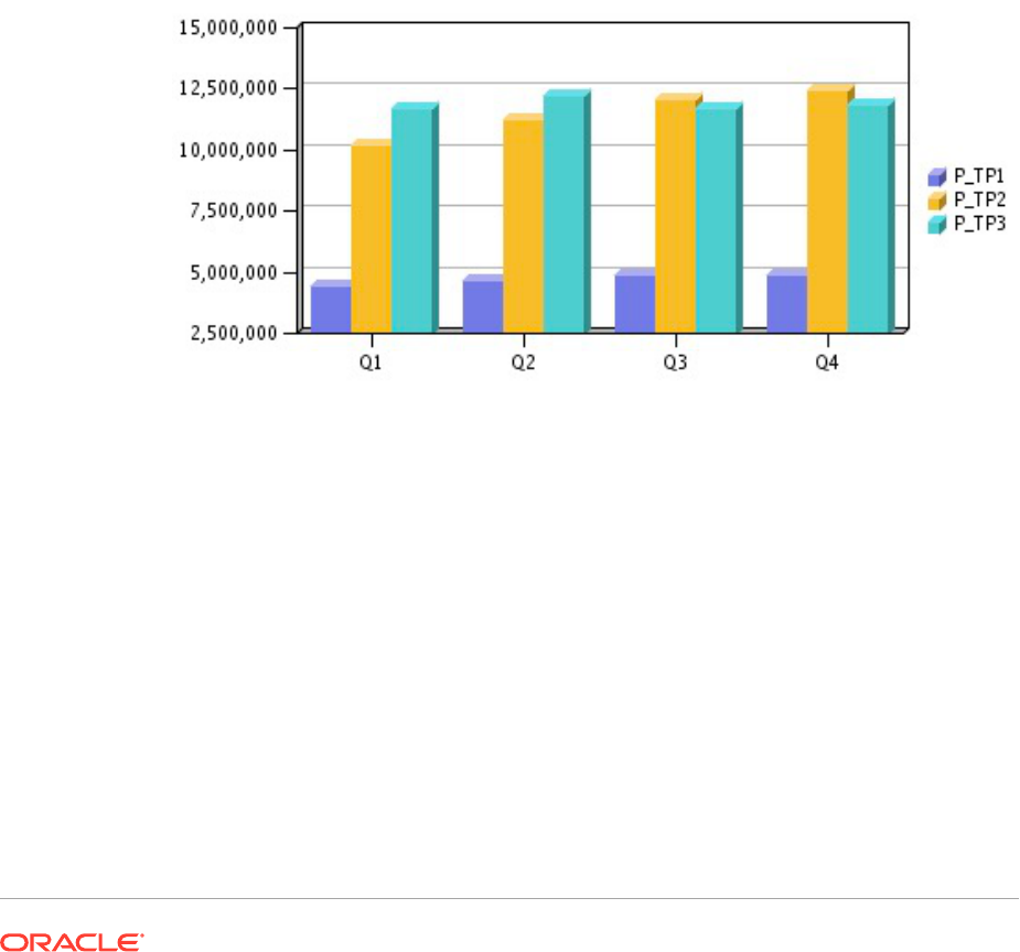
There are inherent differences between the old and new charting product features and
functionality that may affect the rendered chart output and behavior. While best efforts
have been made to keep the existing charting functionality, chart output may differ.
Overall Appearance
Aside from functionality and rendering differences in specific charting user interface
components, the following overall chart rendering differences exist:
• Default Axis Scaling—The default vertical axis scaling (without any custom
ranges specified) may differ.
• Axis Tick Marks—The tick marks that appeared in the vertical and horizontal
axes are no longer supported.
• Default Bar Width—The default bar width differs between the two charting
engines.
• Legend Spacing—The spacing of the chart legend element data sets differs
between the two charting engines.
Figure 6 Overall Appearance in the Original Charting Engine
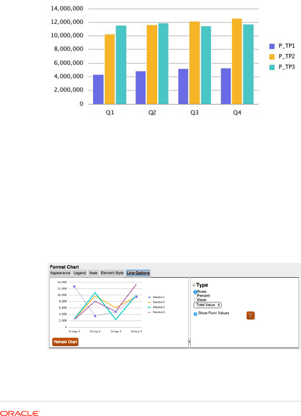
Figure 7 Overall Appearance in the Updated Charting Engine
Chart Data Point Sizing and Display
With the updated charting engine, the display of chart data values and legend labels may
render differently from the original charting engine due to automatic sizing. This behavior
differs by chart type and is dependent on the chart and font size as well as length of the data
point values. In some cases, with chart data point and long legend labels, the chart may need
to be resized and/or the font size reduced to achieve proper display. Additionally, for long
numeric data point values, scaling may need to be applied to shorten the number length.
Line Chart Example
In this example, "Show Point Values" is enabled in the Line Options tab.
Figure 8 Line Options Tab in the Updated Charting Engine
However, the point values in the chart output overlap with the legend.
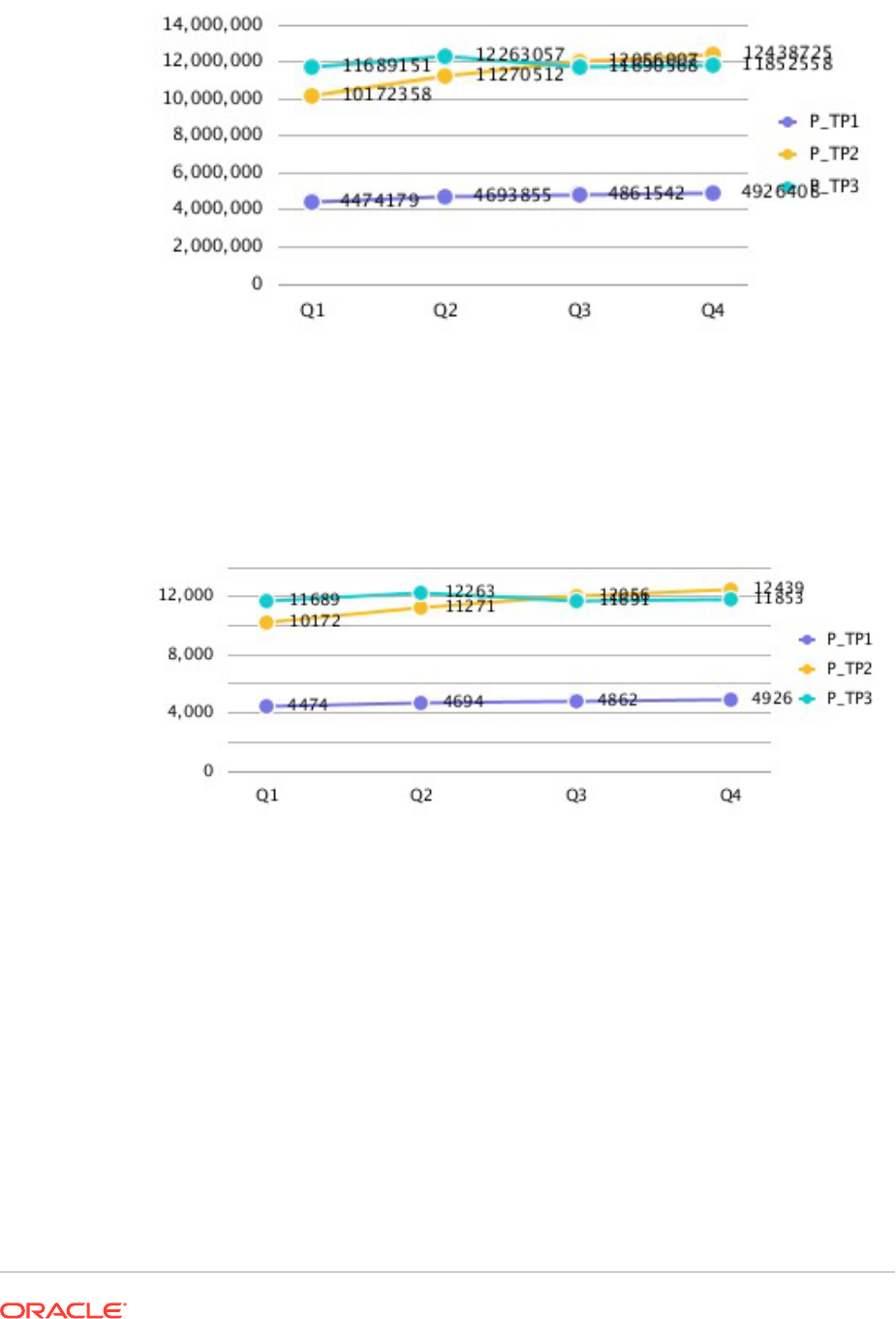
Figure 9 Point Values Overlapping with the Legend
Adjusting the number scaling in the grid to thousands reduces the length of the
numbers and fits the data point values more tightly in the chart.
Figure 10 Point Values Not Overlapping with the Legend
Bar Chart Example
In this example, "Show Point Values" is enabled in the Bar Options tab.
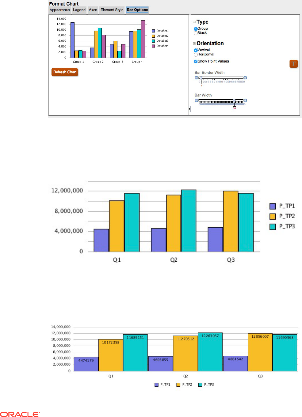
Figure 11 Bar Options Tab in the Updated Charting Engine
However, the point values do not appear in the bar since they are too wide to fit within the
bar.
Figure 12 Point Values Do Not Display in the Bars
Widening the chart size on the report canvas, changing the grid width to 100, and setting the
legend placement to the bottom of the chart fits the long data point values within the chart.
Figure 13 Point Values Display in the Bars
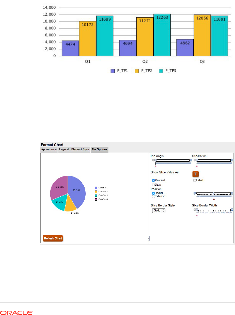
Alternately, adjusting the number scaling in the grid to thousands, placing the legend
on the bottom, and changing the grid width to 90 reduces the length of the numbers
and fits the data point values more tightly in the chart.
Figure 14 Point Values Display in the Bars
Pie Chart Example
In this example, "Show Slice Value As" is set to "Percent", which shows a percentage
data point for each slice of the pie.
Figure 15 Pie Options Tab in the Updated Charting Engine
The data points are cut off or not visible for some slices. In addition, the legend text is
cut off.
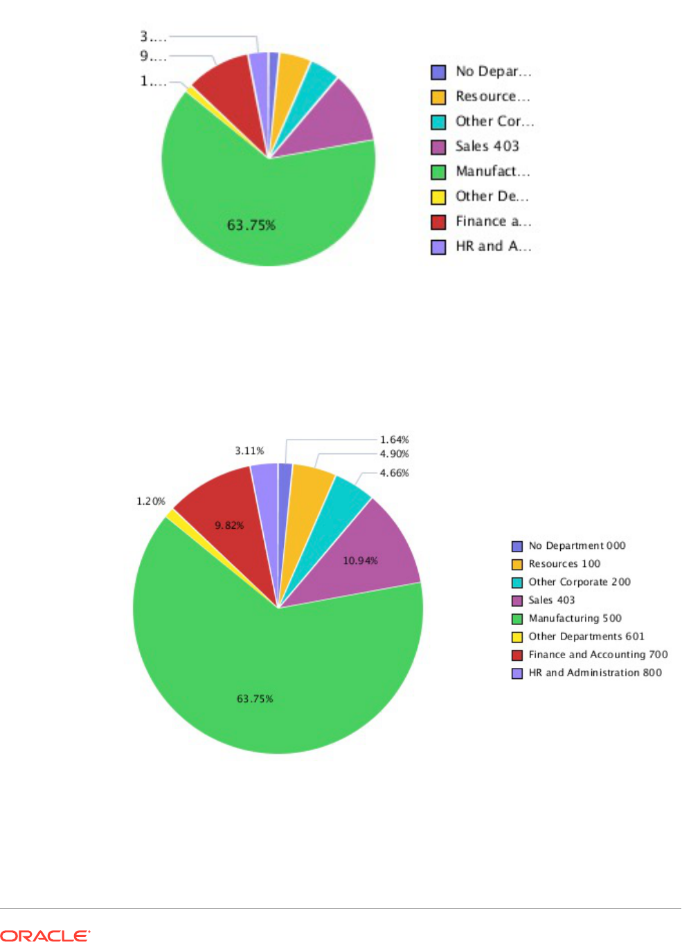
Figure 16 Pie Chart with Legend Data Points Cut Off
By increasing the size of the chart on the report canvas, the entire legend and all data points
are displayed.
Figure 17 Pie Chart Displaying the Legend and All the Data Points
Font Angles
The updated charting engine does not support font angles. All font settings for text in the
Format Chart dialog box do not include a Font Angle setting.
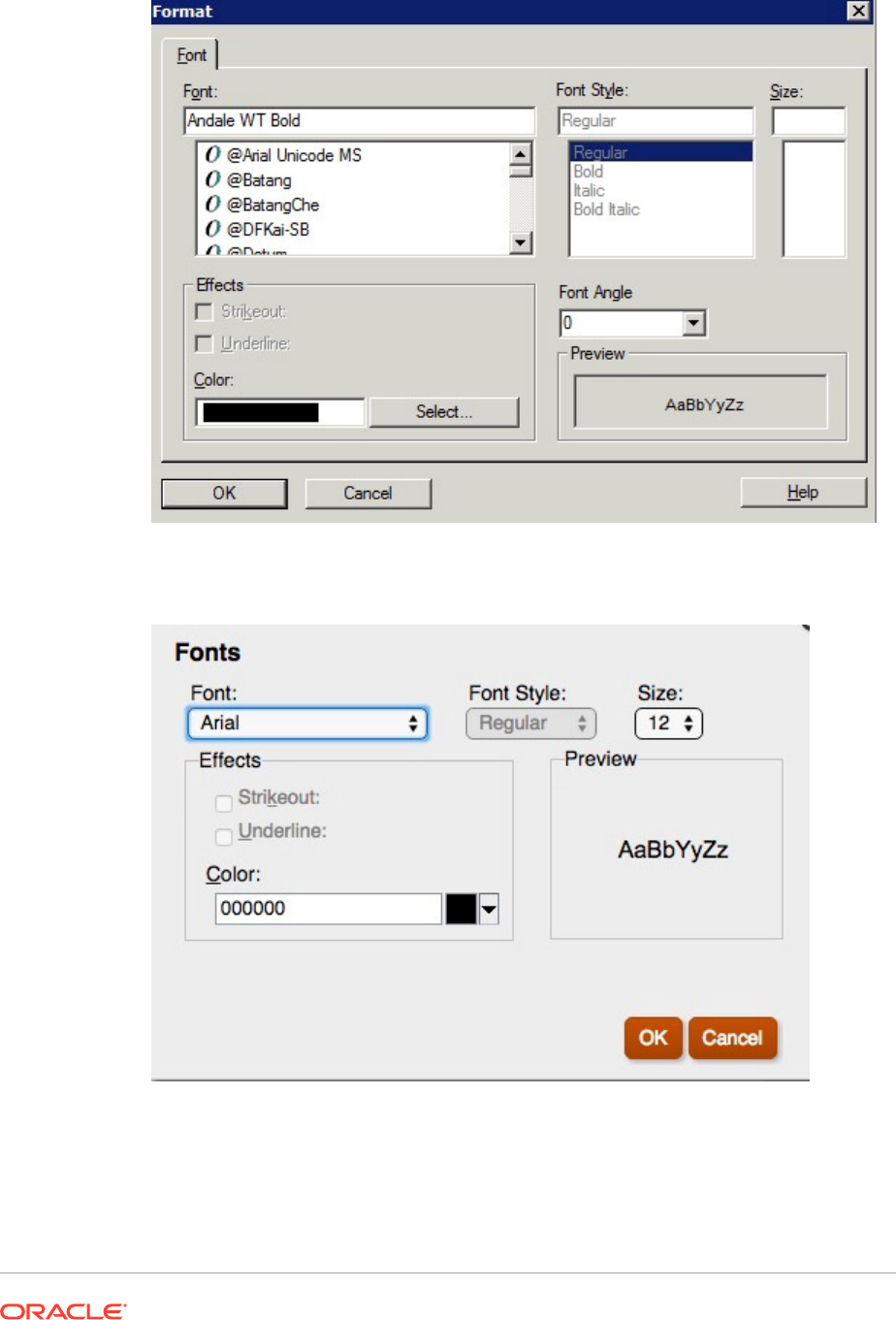
Figure 18 "Font Angle "Setting in the Original Charting Engine
Figure 19 No "Font Angle" Setting in the Updated Charting Engine

Tabs in the Format Chart Dialog Box
Related Topics
• Appearance Tab
• Legend Tab
• Axes Tab
• Element Style Tab
• Bar Options Tab
• Element Style Tab
• Pie Options Tab
Appearance Tab
The following are the differences in the Appearance tab in the Format Chart dialog box:
• Grid Depth—The updated charting engine does not support the 3D appearance for Line,
Bar and Combo charts. Pie charts are either 3D or not, there is no grid depth adjustment.
• Smooth Font Option—The Smooth Font option is not available in the updated charting
engine, since font smoothing is already applied.
• Chart Border—The updated charting engine only supports background color.
Note:
Chart borders are currently not working in the updated charting engine.
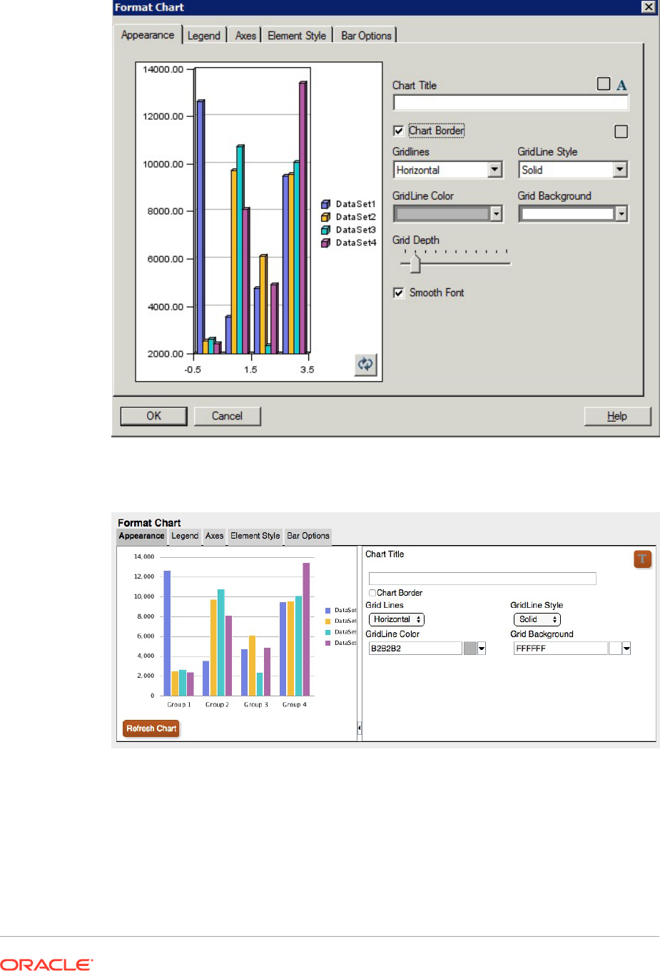
Figure 20 Appearance Tab in the Original Charting Engine
Figure 21 Appearance Tab in the Updated Charting Engine
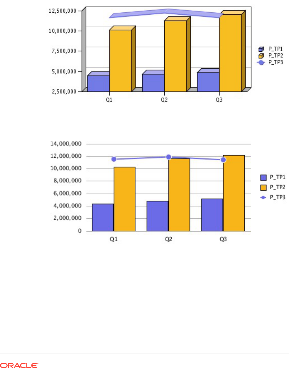
Grid Depth Differences
Figure 22 Grid Depth in the Original Charting Engine
Figure 23 Grid Depth in the Updated Charting Engine
Legend Tab
The following are the differences in the Legend tab in the Format Chart dialog box:
• The updated charting engine supports four "Place Legend" options: Top, Bottom, Left and
Right.
• Middle and Center is always used for placement. For existing charts:
– "Top" is "top and center"
– "Bottom" is "bottom and center"
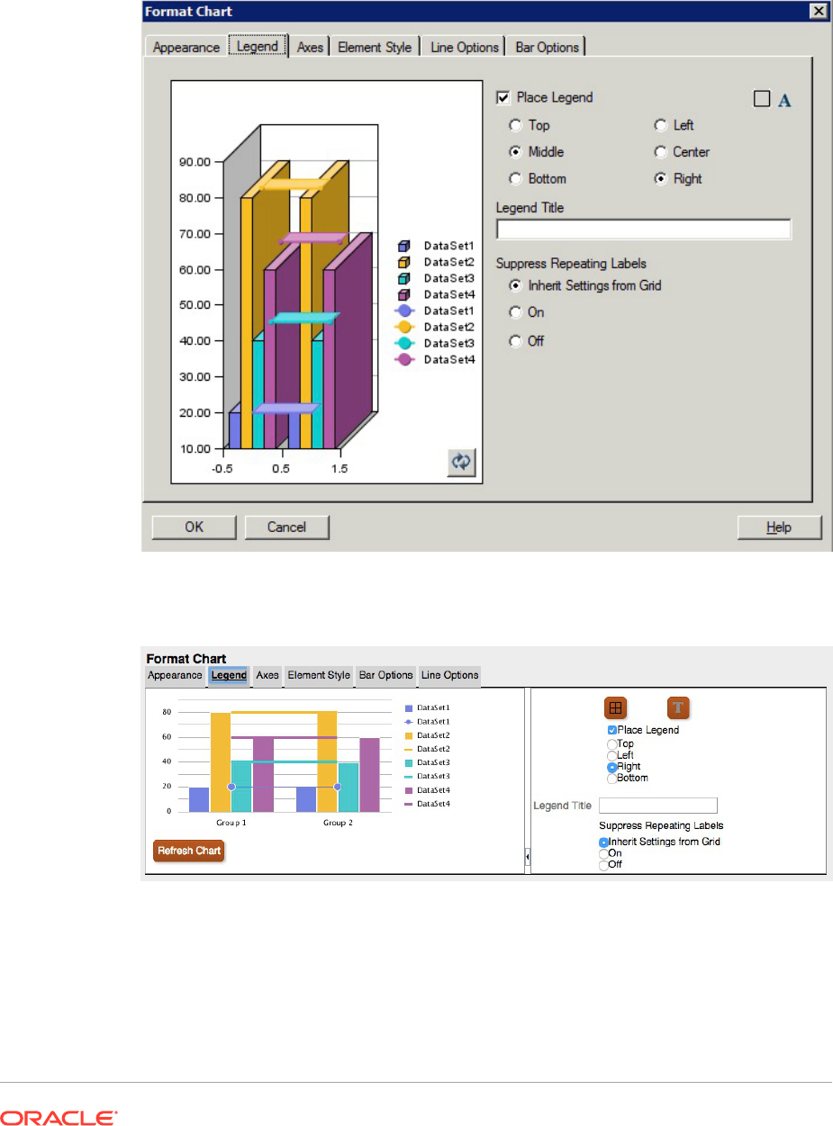
– "Left" is "left and middle"
– "Right" is "right and middle"
Figure 24 Legend Tab in the Original Charting Engine
Figure 25 Legend Tab in the Updated Charting Engine
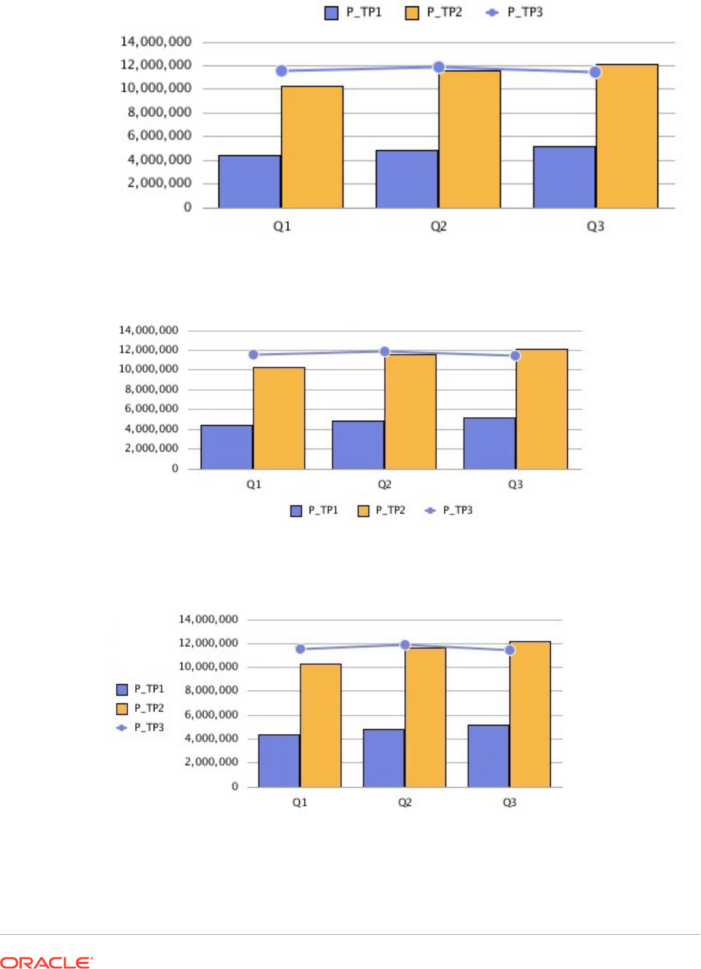
Figure 26 Place Legend = Top
Figure 27 Place Legend = Bottom
Figure 28 Place Legend = Left
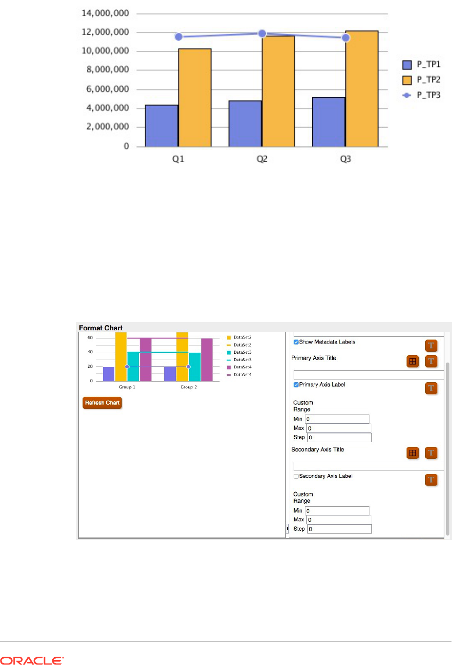
Figure 29 Place Legend = Right
Axes Tab
The updated charting engine only displays the secondary axis for Combo charts.
• Secondary axis data is required for the updated charting engine to display it.
• The original charting engine allowed secondary axis for Bar and Line charts.
Figure 30 Axes Tab in the Updated Charting Engine
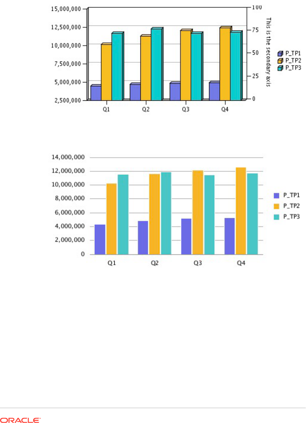
Figure 31 Secondary Axis in the Original Charting Engine
Figure 32 Secondary Axis in the Updated Charting Engine
Element Style Tab
In the updated charting engine, in the Element Style tab in the Format Chart dialog box, each
item is broken out into its own separate section.
Themes
Themes are a new feature that you can define in the Element Style tab in the updated
charting engine.. The following new data element color themes have been added with preset
color selection:
• Classic—Legacy Financial Reporting colors
• BI—Colors from Oracle Business Intelligence charts, affects the first 12 elements
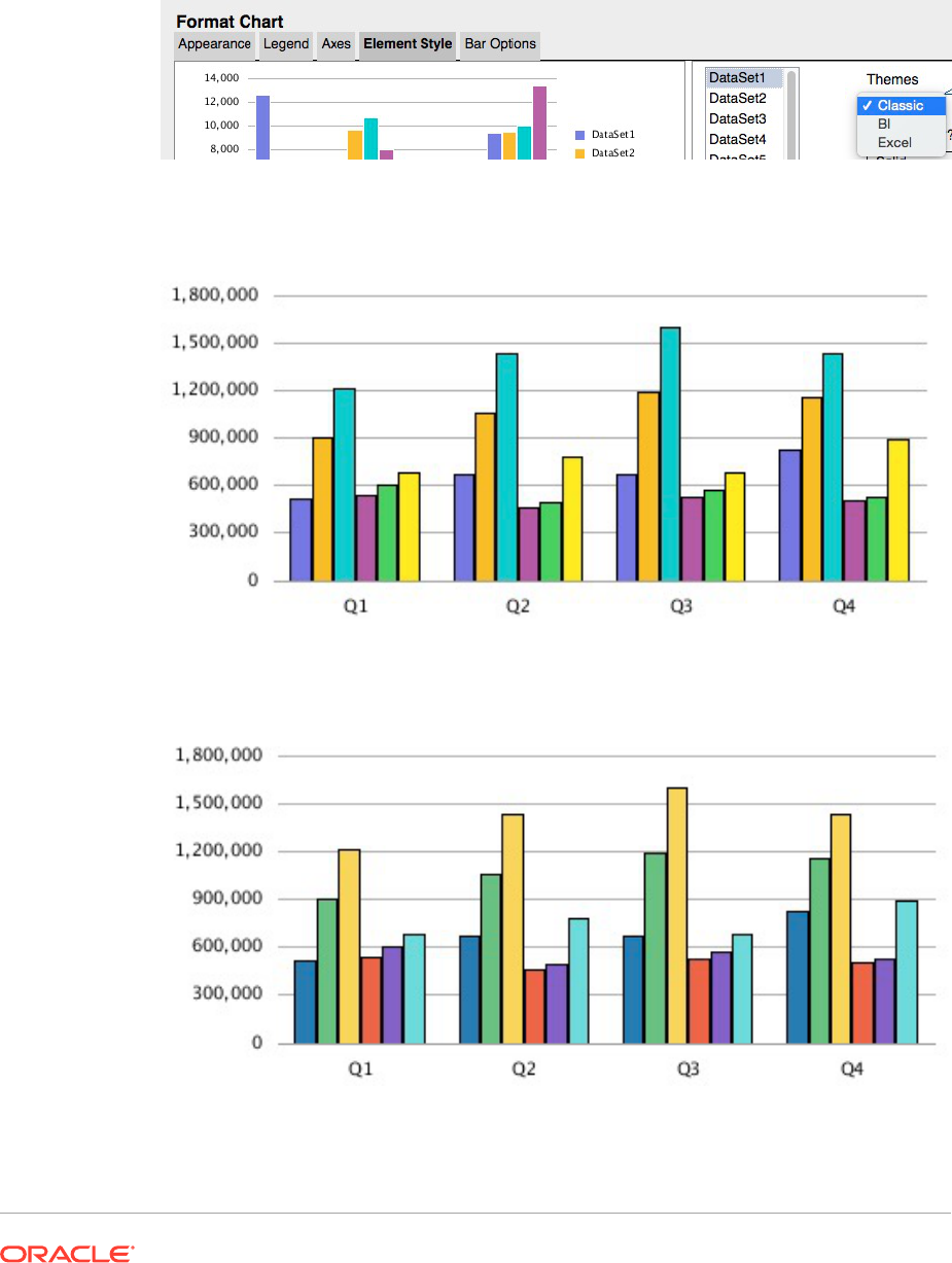
• Excel—Default chart colors from Excel, affects the first 25 elements
Themes are used as a starting point for element colors. You can change the colors for
specific elements in the chart.
Figure 33 Themes in the Updated Charting Engine
Figure 34 Classic
Figure 35 BI
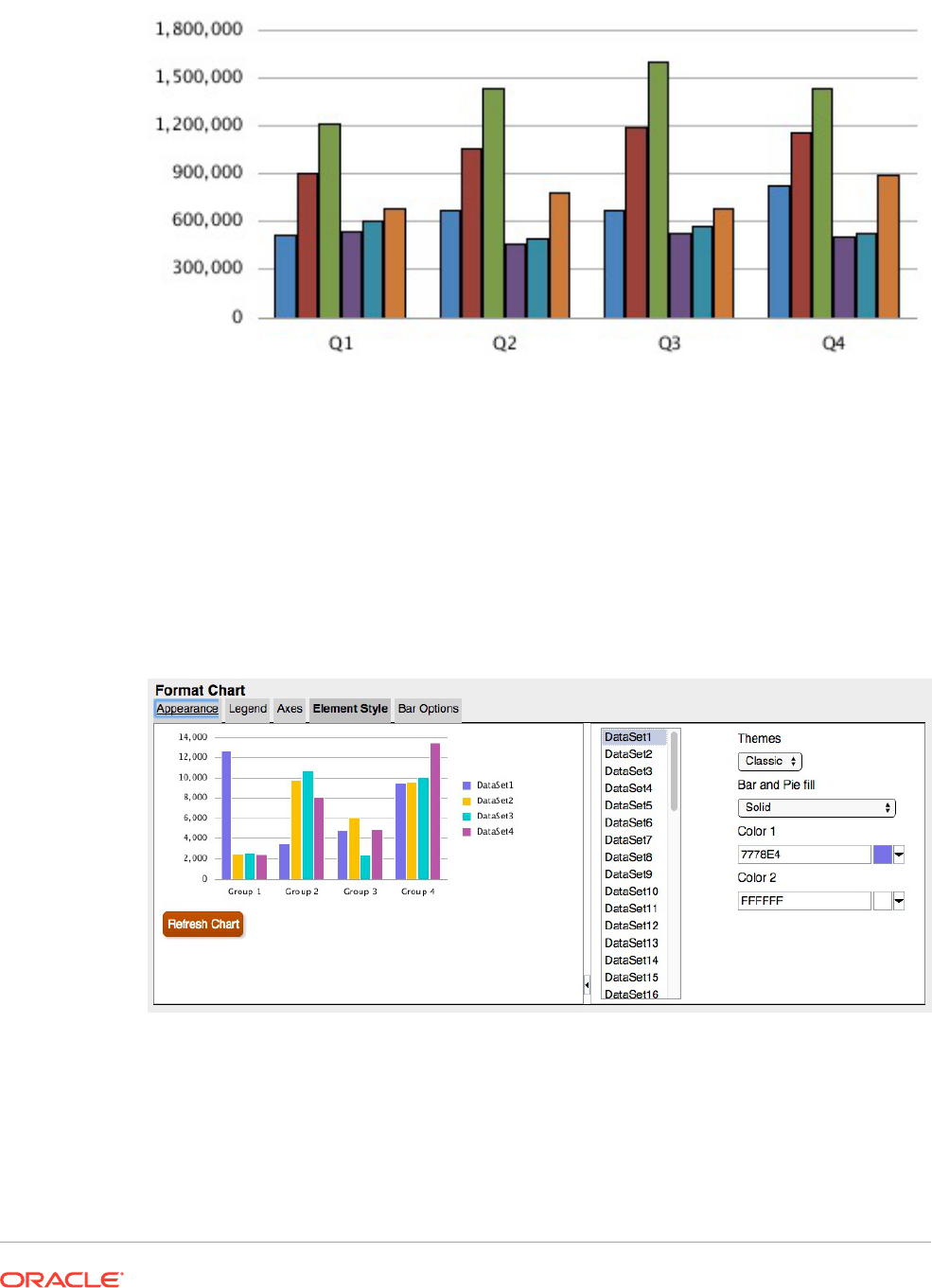
Figure 36 Excel
Bar and Pie Fill
Except for the "Solid" selection, Bar and Pie Fill selections in the updated charting engine
differ in rendering in the original charting engine. All gradient types in the original charting
engine map to the same gradient display in the updated charting engine. Gradient rendering
is subtlety visible only with wide bars in a bar chart or large pie regions. Color 2 is not used
with gradients in the updated charting engine.
Figure 37 Bar and Pie Fill Options in the Updated Charting Engine
The following screen shots illustrate the Bar and Pie Fill differences between the original
charting engine and the updated charting engine from left to right:
• Horizontal
• Vertical
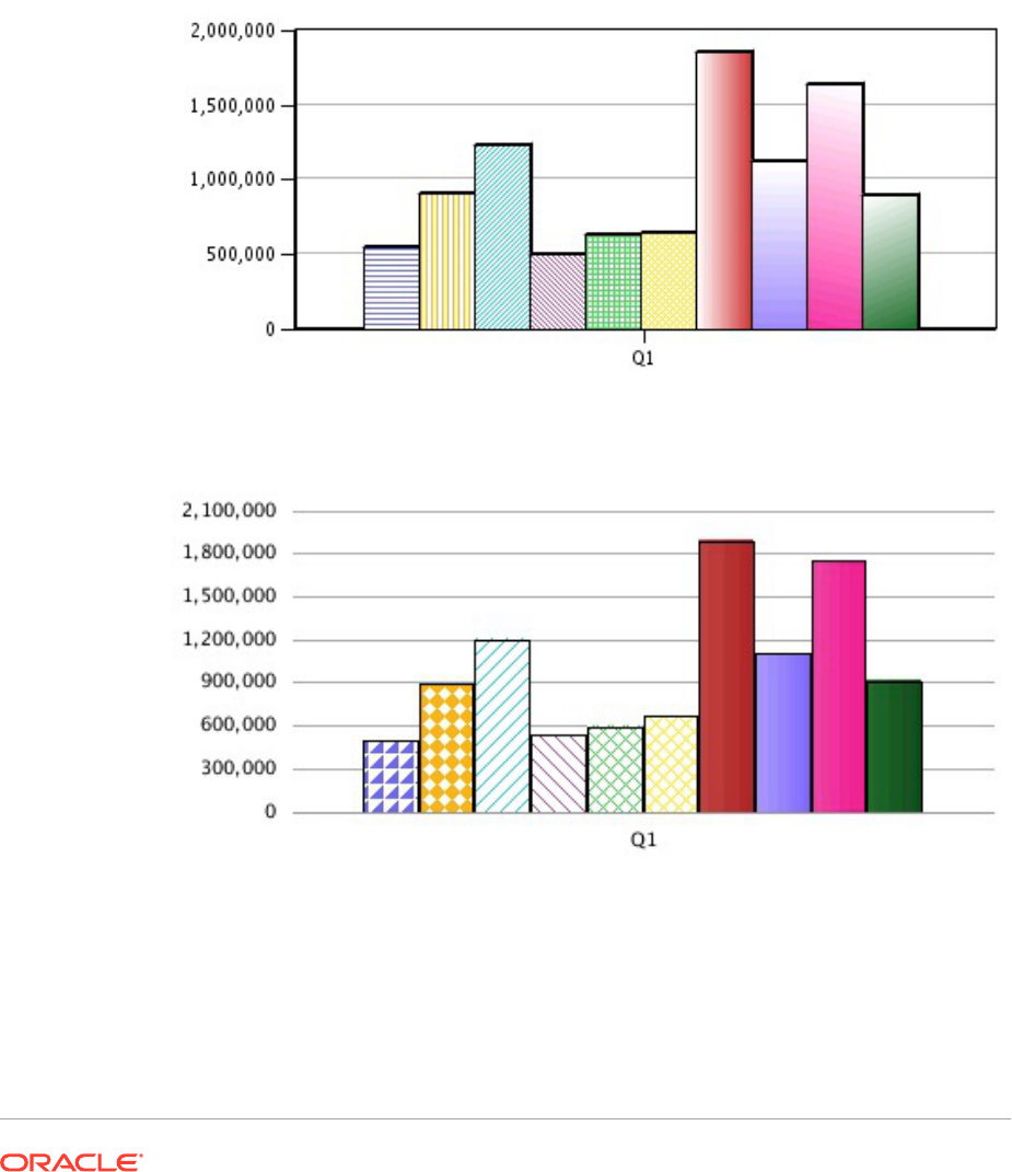
• Forward Slash
• Backward Slash
• Grid Diagonal Grid
• Horizontal Gradient
• Vertical Gradient
• Forward Diagonal Gradient
• Backward Diagonal Gradient
Figure 38 Bar and Pie Fill in the Original Charting Engine
Figure 39 Bar and Pie Fill in the Updated Charting Engine
Bar Shape
Bar shapes (Triangle, Diamond, Cylinder) are not supported in the updated charting
engine.
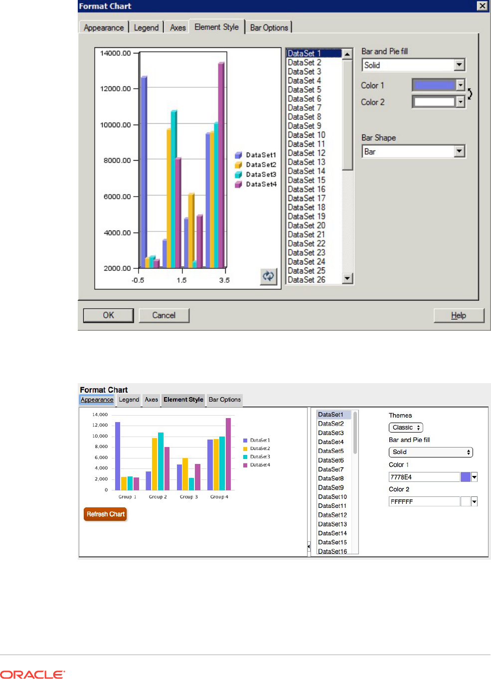
Figure 40 Bar Shape Options in the Original Charting Engine
Figure 41 No Bar Shape Options in the Updated Charting Engine
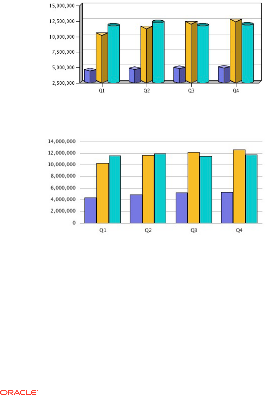
Figure 42 Bar Shapes in the Rendered Output in the Original Charting Engine
Figure 43 No Bar Shapes in the Rendered Output in the Updated Charting
Engine
Bar Options Tab
In the updated charting engine, in the Bar Options tab in the Format Chart dialog box,
each item is broken out into its own separate section.
Type = Rows
The option of "Rows" as a "Type" in the Bar Options tab is not supported in the
updated charting engine, since it is 3D-specific rendering.
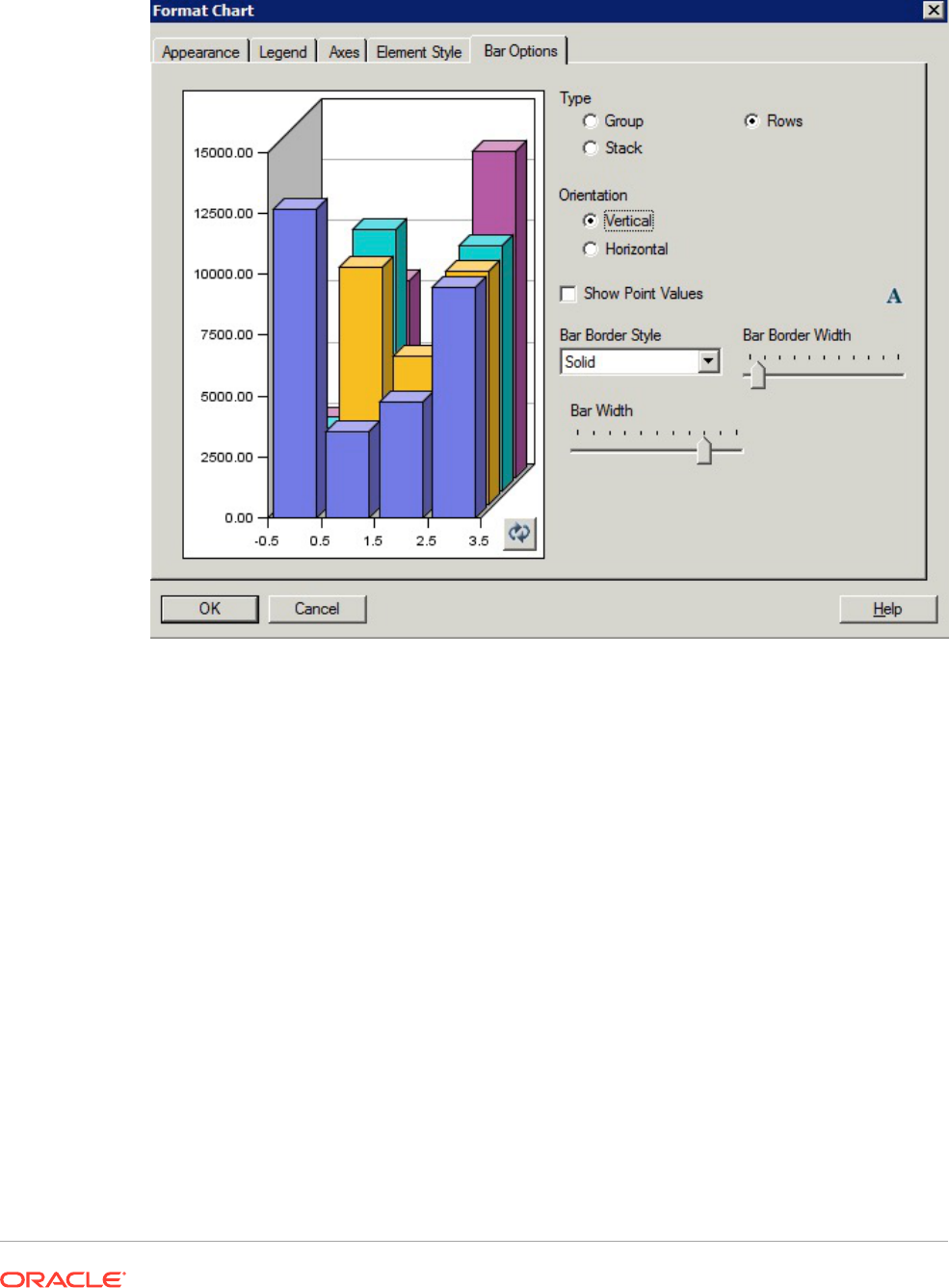
Figure 44 Bar Options Tab in the Original Charting Engine Showing "Rows" as an
Option in "Type"
Bar Border Style
The Bar Border Style of "DotDashed" is not available in the updated charting engine.
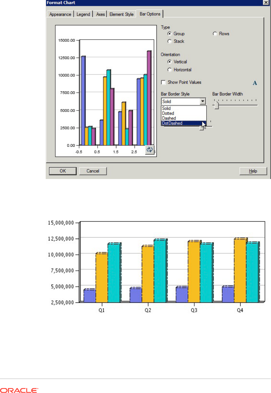
Figure 45 Bar Options Tab in the Original Charting Engine Showing
"DotDashed" as a "Bar Border Style"
Figure 46 Dot Dashed as a Bar Border Style in the Rendered Output in the
Original Charting Engine
Element Style Tab
Differences in Element Style tab for Line charts in the Format Chart dialog box include:
• Dot Dashed as a Line Style
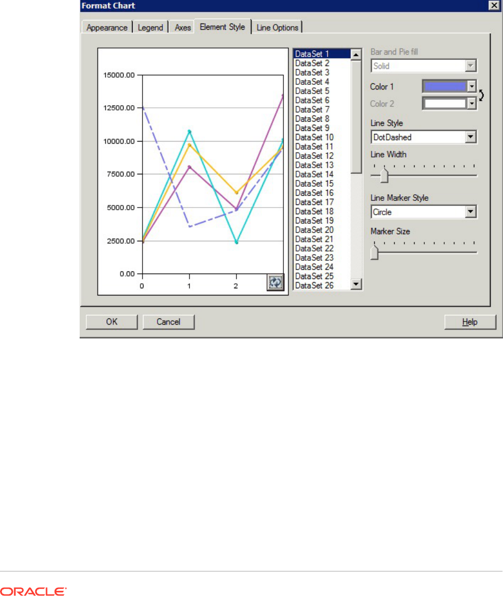
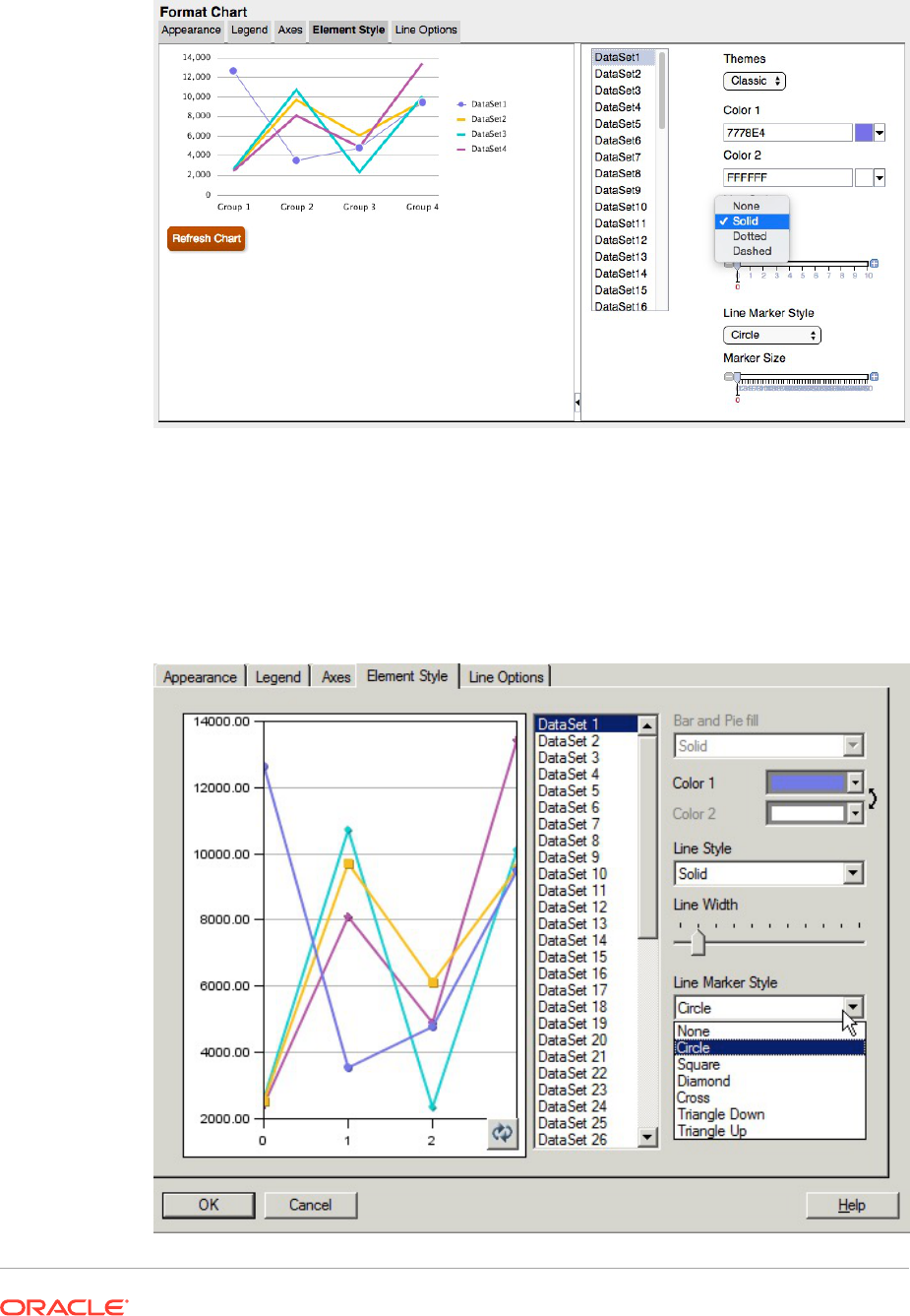
Figure 48 Element Style Tab in the Updated Charting Engine Showing That
There is No "DotDashed" Line Style
Line Marker Styles and Sizing
Line Marker styles and sizing differ between the original charting engine and the
updated charting engine.
Figure 49 Line Marker Styles in the Original Charting Engine
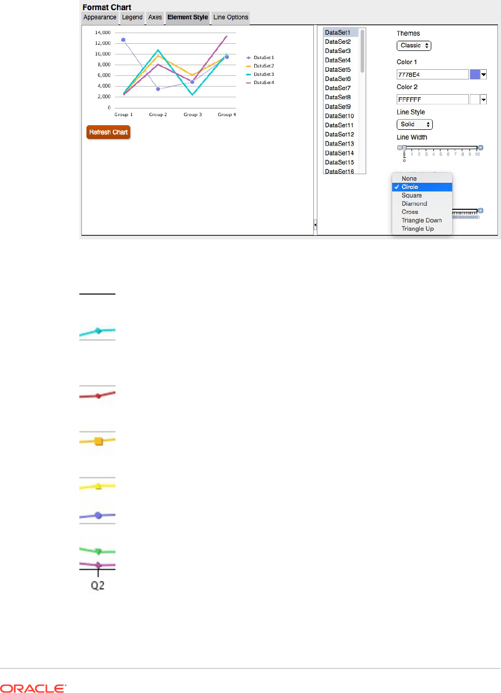
Figure 50 Line Marker Styles in the Updated Charting Engine
Figure 51 Line Markers in the Rendered Output in the Original Charting Engine
Figure 52 Line Markers in the Rendered Output in the Updated Charting Engine
Pie Options Tab
The following are differences in the Pie Options tab in the Format Chart dialog box:
• Pie Angle and Separation—Rendering differs between the original charting
engine and the updated charting engine.
• Show Slice Value As—The original charting engine formats and fits all three
labels if all are selected. The updated charting engine does not adjust Pie to fit
labels; instead, it will crop labels or not display them if the labels do not fit within
the size of the Preview Window or chart output rendering.
• Position—In the updated charting engine, "radial" or "exterior" are supported
without additional adjustments.
With "radial" positioning, if the label cannot fit within the slice, it will either be
placed outside of the slice or not displayed at all.
• Slice Border Style—Only "solid" is supported in the updated charting engine.
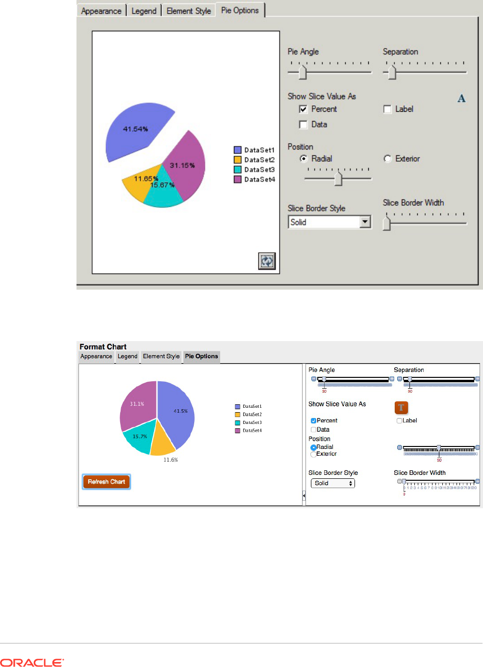
Figure 53 Pie Options Tab in the Original Charting Engine
Figure 54 Pie Options Tab in the Updated Charting Engine
In the updated charting engine, the Grid Depth in the Appearance tab does not adjust the
depth of a Pie chart, it only turns 3D on or off. In addition, separation does not affect one slice
as it does in the original charting engine. In the updated charting engine, all slices have a
smaller and uniform separation.
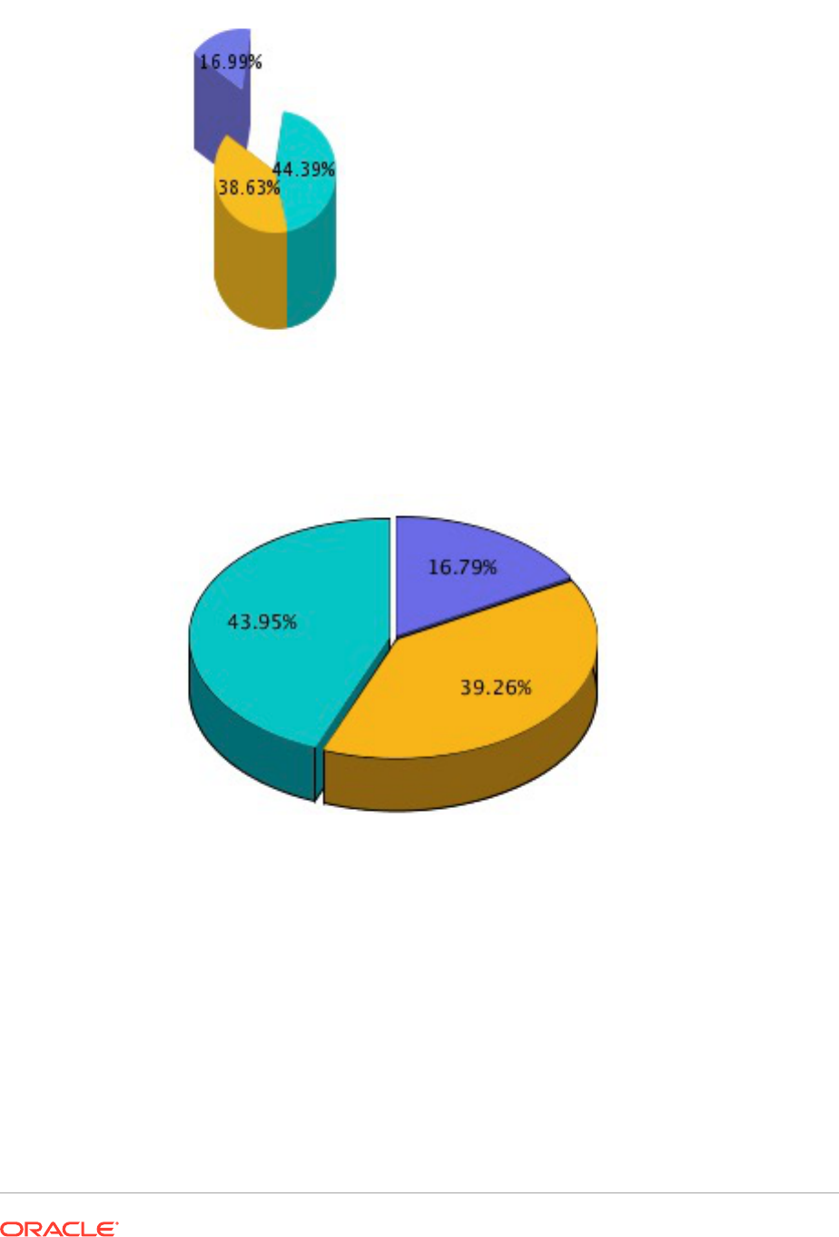
Figure 55 Depth and Grid Separation in the Original Charting Engine
Figure 56 Depth and Grid Separation in the Updated Charting Engine
Defining Members
Related Topics
• About Defining Members
When you specify data for a grid, you set criteria that identifies the data to retrieve.
• Assigning Members
Assign members and member lists to retrieve data for reports.

• Searching For Members
You can perform searches for members to edit.
• Sorting Members
You can sort members within member selection. By default, the members are displayed
in the sort order of the database connection.
• Selecting Members
Use the Select Members dialog box to select the members for your report.
• Selecting Multiple Members
You can select members dynamically based on criteria that you specify.
• Previewing Selected Members
You can preview members or member lists selected for your report before you run it. The
members that you view result from an evaluated member list or function.
• Copying Members Names From a Text Application
You can copy members names from a text application, such as an Excel spreadsheet,
and paste them as new members in the corresponding dimension in Financial Reporting
Web Studio.
• Removing Members
You can remove members from a dimension. Removing members changes the output of
a report, giving you more control over its content.
• Filtering Members
Define filters to view only members that meet your criteria. You can then select from the
filtered list for your report.
• Access Privileges for Members in the Planning Database Source
Financial Reporting Web Studio gives you access privileges on members.
About Defining Members
When you specify data for a grid, you set criteria that identifies the data to retrieve.
You set the criteria by assigning members to the rows, columns, and page axes in the grid, as
well as to the grid point of view and user point of view bars.
You can create lists of reusable members, and use functions to retrieve members
dynamically. Before you define members, you must insert a grid in the report and define its
dimension layout. (See Working With Grids.)
Assigning Members
Assign members and member lists to retrieve data for reports.
Related Topics
• About Assigning Members
• Assigning Members to Data Rows or Columns
• Assigning Members to the Page Axis
• Defining Special Types of Members
• Assigning Members Using Functions

About Assigning Members
Assign members and member lists to retrieve data for your reports. You can select
members to be displayed in your report, or you can use functions to select dimension
members dynamically. You can insert a separate row or column in a grid for each
selected member, or you can place all of the selected members in one row or column.
Assigning Members to Data Rows or Columns
To assign members to data rows or columns:
1. Open a report and select a grid.
2. Open the Select Members dialog box by doing one of the following:
• Double-click a dimension in the grid.
• Select a dimension in the grid, and then click the button in the formula bar with
the dimension name.
3. In the Select Members dialog box, select the members, members lists, or
functions to assign to the selected data row or column.
4. Optional: To insert a row or column for each selected member, select Place
selections into separate rows (or Columns).
5. Click OK.
Assigning Members to the Page Axis
You can assign members to the page axis of a grid. When you select members for the
page axis and run the report, a grid is generated for each page member. If a chart
references a grid with multiple page members, a new chart is generated for each page
member.
For example, assume that you assign the following members in the Scenario and
Entity dimensions to the page axis:
• Target 1 and Target 2 in the Scenario dimension
• Radio Promotions and Web Promotions in the Entity dimension
When you view the report, it is formatted and populated with data from all
combinations of members on the page axis. The report contains four grids, one for
each page member combination.
In this example, you could select any combination of the members:
• Target 1: Radio Promotions
• Target 1: Web Promotions
• Target 2: Radio Promotions
• Target 2: Web Promotions

Note:
In Financial Reporting, all the members and corresponding data in the page axis
are retrieved when the report is run. As a result, performance may be impacted for
reports with a large number of members on the page axis.
To assign members to the page axis:
1. Open a report and select a grid.
2. In the Pages drop-down list, select a dimension.
3. On the formula bar, select the button with the dimension name.
If you know the member names for a dimension, enter the member name into the formula
bar text area. For example, for a "Measures" dimension, you could enter "Profit, Sales".
Click to verify the member selection.
4. In the Select Members dialog box, select the members to use on the page axis, and then
click OK.
Defining Special Types of Members
You can use the Select Members dialog box to select the following types of members:
• Prompt—Acts like a variable that asks you to select members when you run a report.
You determine the dimension and defaults at design time, and you select the members
when you generate the report. Prompt also enables the report writer to filter the
dimension members that are available to select when running the report.
• Same As—Creates a column or row member selection with the same member selection
setting as another column or row.
• Current Point of View—Acts as a variable that employs the point of view to specify the
member of a dimension when the report is run.
• User Point of View—Can be selected as a member in the book point of view. The
parameters can be modified by the end user.
Setting Up Report Prompts
A prompt is a way of assigning members to a dimension. The prompt is set up during design
time. As a report designer, you can limit the type of data to assign to a dimension. You can
also specify whether the Respond to Prompts dialog box displays member names,
descriptions or aliases, or both member names and descriptions or aliases.
For example, you could create a report that enables the user to select from lines of products.
The report designer selects Prompt as a member of Product, and then selects specific
product lines. The person who runs the report then selects from those product lines.
To set up a report prompt for members:
1. Open a report and select a grid.
2. Double-click the dimension cell for which you want to assign a prompt.
3. In the Select Members dialog box, on the Members tab, select Prompt for
<dimension name>, and then click to select it.
4. Click OK.
5. In the Define Prompts dialog box, enter the following information:
• Title—Enter the title for the prompt.
For example, for a "Measures" dimension, you could say "Enter Measures".
• Default Member—Enter the member to use as the default member, or click
to select the default member. If you specify multiple members as the
default, separate the members by commas.
If you leave Default Member blank, the Respond to Prompts dialog box
does not display a default member when you run the report or create a batch.
• Choices List—Click to select the member or members available as
choices when responding to the prompt. If you specify multiple members in the
choices list, separate the members by commas.
• Select which labels to display in the Respond to Prompts dialog box when
you run the report (Member Name, Alias, or Member Name and Alias).
6. Click OK.
Setting Up Same As References
Using a Same As reference, you can select a member from another row or column.
The following characteristics apply to a Same As reference:
• In a report, members referred to by Same As are always from the same
dimension, type of database connection, and grid.
• Members referred to by Same As are only available for member selection in rows
and columns in a grid. Same As cannot be used as member selection in:
– Page Axis
– Grid POV
– User POV
– Book POV
– Batches POV
– Default member selection for a prompt
– Response to a prompt
– Member function member parameter, such as range
– Member selection in the book editor
• Same As can reference a row or column that gets its member selection from a
prompt or Current POV.
• Same As cannot reference another Same As reference.
• Same As is not supported within row and column templates.
• Same As must be used alone and cannot be combined with any other member
selections.
To set up a Same As reference:
1. Open a report and select a grid.
2. Double-click a dimension cell.
3. In the Select Members dialog box, on the Members tab, expand Same As Member
Selection in, then select Same As Column Name or Row Name , and then click to
add the column or row to the area selected in the grid.
4. Click OK.
Setting Up a Current Point of View
A current point of view enables you to obtain a member for a row, column, or page from the
user point of view.
To set up a current point of view:
1. Open a report and select a grid.
2. Double-click the dimension cell for which you want to set up a current point of view.
3. In the Select Members dialog box, on the Members tab, select Current Point of View
for <dimension name>, and then click to select it.
4. Click OK.
Assigning Members Using Functions
You can use functions to select members dynamically. After you select a function, you can
edit its parameters.
To assign members using functions:
1. Open a report and select a grid.
2. Double-click a dimension cell.
3. In the Select Members dialog box, select the Functions tab.
4. Highlight one or more functions, and then click
.
You cannot select functions that do not require parameter values, such as
BottomofHierarchy, TopofHierarchy, AllMembers, and SuppressSharedMembers.
5. Select a function, and then click .
6. Click
, and the select the members to add to the function.
Functions Available Through Member Selection and the Formula Bar
The functions listed in Table 1 can be selected from the Functions tab in the Select Member
dialog box, and they can be entered dynamically in the formula bar.
Table 5 Functions Available Through Member Selection and the Formula Bar
Function Parameters Needed Description
AllMembers All Members in Hierarchy
dimension
Members of the specified dimension
Ancestors Ancestors of member (Inclusive) Members at all levels above the specified member
BottomOfHierarchy Bottom of Hierarchy dimension All Level 0 members
TopOfHierarchy Top of Hierarchy dimension Top-level member of hierarchy
Children Children of member (Inclusive) Members one level below the specified parent
Descendants Descendants of member
(Inclusive)
Members at all levels below the specified parent
Parent Parent of member (Inclusive) Member one level above the specified member
Siblings Siblings of member (Inclusive) Members with the same parent as the specified member
Member member The specified member
Members N/A Members of the current dimension
OfSameGeneration Same generation as member Members of the same dimension and generation as the
specified member
OnSameLevelAs Same level as member Members from the same dimension and on the same
level as the specified member
Note: In Planning, OnSameLevelAs only works with
level 0 members.
SameLevelAs N/A Members of the same level
SystemMemberList System-defined Member List
Lev(n),dimension
Members in a specified system-defined member list
Functions Available Only Through Member Selection
The functions listed in Table 1 can be selected from the Functions tab in the Select
Member dialog box. They cannot be entered dynamically in the formula bar.
Table 6 Functions Available Only Through Member Selection
Function Description
Match Extracts members that match a specified pattern or set of characters.
Note:
When using the asterisk (*) wildcard, the
pattern can contain only one asterisk and it can
only appear as the last character.
Property Extracts members with the specified property value.
Range Defines a range of members.
For example, you can use the "Year" dimension to specify all months in the
first quarter by selecting "January" as the start member and "March" as the
end member.
Searching For Members
You can perform searches for members to edit.
You can search using a text string or by property (that is, name and description). You can also
use a blank space as a separator to perform simultaneous searches. If you enclose a string
of characters in quotation marks, the system searches for an exact match, including the blank
spaces between the characters.
To search for a member:
1. Open a report and select a grid.
2. Double-click a dimension cell.
3. In the Select Members dialog box, next to Find, click the drop-down to select an option,
and then enter the text for which to you want to search.
4. Click .
Tip:
Use Wildcards is automatically enabled during member selection. When using
wildcards, use ? to represent a single character search, and use * for a multiple
character search.
If the search criteria has a space in it, enclose the search phrase in double quotes.
For example, *IC Offset* should be "*IC Offset*".
Sorting Members
You can sort members within member selection. By default, the members are displayed in the
sort order of the database connection.
You can sort selectable members in a preferred order, and you can sort the members that are
selected to match the row or column order of data in your report. The order in which selected
items are displayed in member selection is the order in which they are evaluated and
displayed in the report.
You sort the members by property and display them in ascending or descending order. By
default, the system sorts the list numerically, then alphabetically.
You can enable the system to sort the list whenever the view changes, or you can sort the list
manually.
To enable the system to sort the list whenever the view changes:
To sort members manually:
1. Open a report and select a grid.
2. Double-click a dimension cell.
3. In the Select Members dialog box, select the Lists tab.
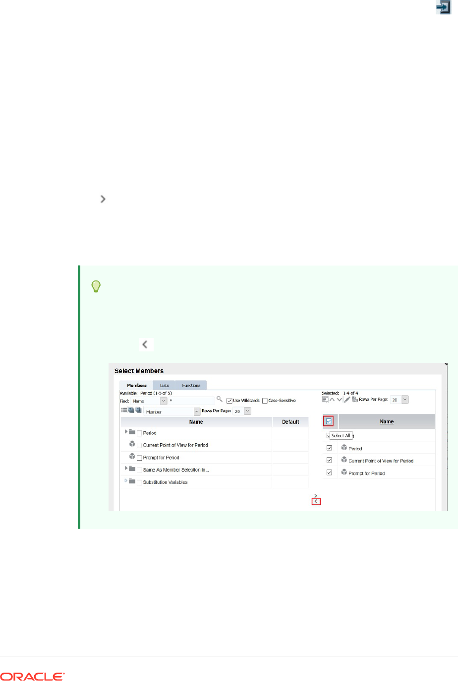
4. In the Lists tab, click View, and then select Sort.
5. In Sort (dimension) Items, select the property for the primary sort, then click .
6. Click OK twice.
Selecting Members
Use the Select Members dialog box to select the members for your report.
To select the members for a report:
1. Open a report and select a grid.
2. Double-click a dimension cell.
3. In the Select Members dialog box, in the Members tab, select a member or
members, and then click the right arrow button
(
).
4. Select whether you wish to Place selections into separate columns.
5. Click OK to save your selections.
Tip:
If you have a report or a book with several members and wish to update the
report or book and remove all of the members; instead of selecting each
member individually, click the Select All check box, and then click the left
arrow ( ) to remove all the members from the report or the book.
Selecting Multiple Members
You can select members dynamically based on criteria that you specify.
You define criteria by creating expressions of members, boolean operations, and
commands.
Boolean operators enable you to specify precise member combinations for the report, which
is useful for dealing with large volumes of data. Use the
AND
,
OR
,
UNION
, and
NOT
boolean
operators, combined with expression commands, to refine your member selections.
To select multiple members based on criteria:
1. Open a report and select a grid.
2. Double-click a dimension cell.
3. In the Select Members dialog box, in the Members tab, select at least two members,
and then click .
You must select at least two members before you can create criteria.
4. In the Selected area of the dialog box, build expressions by using one or more of the
following operators and symbols:
• Select Not to add the Boolean operator
NOT
to the expression.
NOT
is the inverse of
the selected condition.
• Enter a left parenthesis, (, to add an opening character to the expression.
• Enter a right parenthesis, ), to add a closing character to the expression.
• In the Operator column, select And, Or, or Union.
Tip:
If you are using three members, use two pairs of parentheses. For example, if you
select descendants of Market and you want to exclude East, West, and South, your
advanced member selection query should be as follows:
Descendants of Market AND NOT (East AND NOT (West AND NOT SOUTH))
Previewing Selected Members
You can preview members or member lists selected for your report before you run it. The
members that you view result from an evaluated member list or function.
To preview members:
1. Open a report and select a grid.
2. Double-click a dimension cell.
3. In the Select Members dialog box, in the Selected area, click
.
Copying Members Names From a Text Application
You can copy members names from a text application, such as an Excel spreadsheet, and
paste them as new members in the corresponding dimension in Financial Reporting Web
Studio.
For example, you could copy the members names in the "Year" dimension in an Excel
spreadsheet to a grid in Financial Reporting Web Studio that contains the "Year" dimension.
To copy members names from an application to Financial Reporting Web Studio:
1. Open the source application and select the members to copy.
2. In Financial Reporting Web Studio, open a report and select a grid.
3. Select the dimension cell to which you want to copy members.
4. In the formula bar, clear the content, then right-click, and then select Paste.
5. Edit the text in the formula bar by adding commas between members.
6. Click to verify the member names.
Removing Members
You can remove members from a dimension. Removing members changes the output
of a report, giving you more control over its content.
To remove members that are contained in a single cell:
1. Select the cell containing the members.
2. Do one of the following:
• Double-click the dimension name to display the Select Members dialog box,
select the member or members to remove, and then click the left arrow (
) to
remove the member or members from the Selected area of the dialog box. To
remove all the members, click the Select All check box, and then click the left
arrow.
• Select the dimension in the grid, and then remove the member from the
formula bar.
To remove members that are in separate rows or columns:
1. Right-click the row or column.
2. Select Delete.
Filtering Members
Define filters to view only members that meet your criteria. You can then select from
the filtered list for your report.
For example, you can display Regions in the United States division only. Filters are
useful for reducing the number of members that are displayed.
To define filters:
1. Open a report and select a grid.
2. Double-click a dimension cell.
3. In the Select Members dialog box, in the Members tab, right-click inside the
Available area and make one of the following selections:
• Select Filter, and then Custom, highlight the lists of available functions, then
click the Add button,
, to move them to the Selected area.
• Select Filter, and then Predefined, then highlight the desired list.
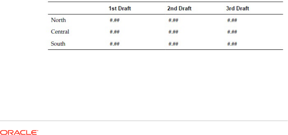
4. Click OK.
5. Click OK to return to your report.
Access Privileges for Members in the Planning Database
Source
Financial Reporting Web Studio gives you access privileges on members.
Access privileges are available on members in the following dimensions:
• Accounts
• Entities
• Scenarios
• Versions
In the Select Member dialog box, all members for the Planning database connection are
listed regardless of access privileges. Therefore, you can place members on a grid that are
not returned when the report is run. The members you choose affect the output of the report.
For example, if you select a member to which the user cannot access in the Point of View or
Page Axis, an error message is returned.
The following four scenarios describe what values are returned on a grid that contains valid
and invalid dimensions or members. These scenarios assume that you are reporting against
a Planning database connection and have access privileges to the following dimensions and
members:
• Accounts: Sales, Profit
• Versions: 1st Draft, 3rd Draft, Final Version
• Entities: North, Canada
• Scenarios: Budget
Scenario 1
You run a report based on the following grid:
Page: Budget
Because you do not have access to Central, South, and 2nd Draft, the report returns the
following results:
Page: Budget
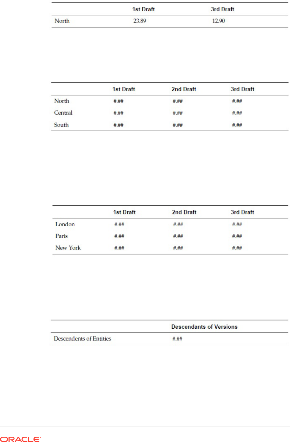
Scenario 2
You run a report based on the following grid:
Page: Actual
Because you do not have access to the Scenario dimension in the Pages axis of the
grid, the member Actual is in the Scenario dimension, no page is displayed and an
error message describing your access privileges is returned.
Scenario 3
You run a report based on the following grid:
Page: Budget
Because you do not have access to the entities on the rows, no page is displayed and
an error message describing your access privileges is returned.
Scenario 4
You run a report based on the following grid:
Page: Budget
The report returns the following data:
Page: Budget

Formatting Reports
Related Topics
• About Formatting Reports
Format reports to specify how report components, such as text boxes, grids, images, and
charts are displayed.
• Formatting Best Practices
There are several things to keep in mind when formatting a report.
• Changing the Page Setup
You can alter page settings that control how reports are printed or viewed.
• Using Conditional Formatting
Use conditional formatting to apply specific formatting to cells in a grid.
• Using Conditional Suppression
Use conditional suppression to suppress the display of rows, columns, or grids.
About Formatting Reports
Format reports to specify how report components, such as text boxes, grids, images, and
charts are displayed.
For example, you can specify fonts and add borders. When you format a report, you define
the properties of the components. The formatting you apply affects the printed and online
report presentation.
Note:
Each object has default formatting properties. You can use the default format
properties if you do not want to format your report.
Formatting Best Practices
There are several things to keep in mind when formatting a report.
• Cell formatting has precedence over row and column formatting and grid formatting.
• Cell formatting allows you to make exceptions to row and column formatting and grid
formatting.
• Row/column formatting has precedence over grid formatting.
• Row/column formatting allows you to make exceptions to grid formatting.

• Conditional formatting takes precedence over all other formatting and replaces
formatting previously set at the grid, row and column, or cell level. For example, if
you use conditional formatting to change cell colors, and want to retain a specific
number of decimal places applied with regular formatting, you must specify both
formats using conditional formatting.
• The correct sequence in formatting a report is:
1. Format the grid.
2. Apply different formatting to rows and columns.
3. Apply specific cell formatting.
Changing the Page Setup
You can alter page settings that control how reports are printed or viewed.
You can change the paper size, page orientation, heading display settings, default
width and length for the report, and create a custom size for the work area. You can
also specify whether cell documents print with consecutive page numbers or print the
page settings on each document.
To change the page setup:
1. Open a report and select File, and then Page Setup.
2. Define information in the tabs in the Page Setup dialog box, and then click OK.
Note:
When you print a report with cell document attachments enabled (see
Attaching Cell Documents in a Report), the file attachment page numbers
can be renumbered to reflect the page numbers of the report. For example, a
nine page report with a five page Word document attached can renumber the
Word document output to reflect the page number 10 to 15.
To print consecutive page numbers on cell documents, in the Page Setup
dialog box on the Page tab, select Consecutive Page Numbers. To print the
page numbers as specified on each cell document, clear Consecutive Page
Numbers.
Using Conditional Formatting
Use conditional formatting to apply specific formatting to cells in a grid.
Related Topics
• About Conditional Formatting
• Applying Conditional Formatting
• Changing the Order of Conditional Formats
• Deleting Conditional Formats
• Deleting Conditions

• Conditional Formatting Example
About Conditional Formatting
Use conditional formatting to apply specific formatting to cells in a grid. For example, assume
you define "current cell value = 0" and then define a format to change the color of the cell font
to blue if the criteria is met. If the data returned for the cell has a value of 0, then the font
color is changed to blue.
Conditional formatting takes precedence over all other formatting and replaces formatting
previously set at the grid, row or column, or cell level. For example, if you use conditional
formatting to change cell colors, yet want to retain a specific number of decimal places
applied with regular formatting, you must specify both formats using conditional formatting.
You can apply conditional formatting to enhance your reports. For example, you could
underline any values greater than 1000. You can also set up more complex conditional
formatting. For example, if the account type equals expense and the current cell value is
greater than 1000, you could apply bold to the cell. In addition, if the value of a product cell is
less than 1000, you could set the background color of the cell to green.
The manner in which you use conditional formatting can impact performance depending on
the size of the report. Performance is also contingent on the criteria used and the frequency
of use. All of these factors combined can affect performance. Criteria such as Data Value,
Member Name, and Member Alias/Description are faster because they are part of the
metadata or data query. Data Value comparisons are the fastest. Avoid criteria such as
Generation, Level, Account Type, and Attribute Value whenever possible, as performance is
slower because those criteria are not part of the regular metadata or data query.
Applying Conditional Formatting
When you apply conditional formatting to cells in grids, you establish a condition for the
selected cells, and then you specify formatting for values that meet that condition.
In a grid, each cell with conditional formatting contains a colored dash indicating that a
conditional format is applied to the cell.
You can specify conditionally formatting for related content on any grid object cell. For
example, if the Market member name is "East" link to"ReportA" , if the Market member is
"West" , link to "ReportB". In the Format Cells dialog box, you can specify the related content
links.
To apply conditional formatting:
1. In a grid, select a cell or cells, and then do one of the following:
• Click
.
• Right-click a cell, and then select Conditional Format.
2. In the Conditional Format dialog box, define the condition.
a. For Condition1: If, select a property value from the drop-down.
b. Depending on the property value you select, you may be able to enter a reference
value.
You can type in a value, or click the drop-down to change the value if desired. For
example, if you select "Cell Value," then the reference value is automatically
populated with "A,1." At this point, you can keep this value or type in a new value. If

you select "Generation," then the reference value is automatically populated
with "Period." At this point, you can keep this value, or click the drop-down to
select a new value.
c. Select a comparison operator:
• = (equal to)
• < > (less than or greater than)
• > (greater than)
• > (greater than)
• > = (greater than or equal to)
• < = (less than or equal to)
• equals (is equal to)
• not equals (is not equal to)
• starts with
• ends with
• contains
• is
d. Select a comparison option:
• Value—Enables the assignment of a certain value to a cell.
• Cell Value—Returns the cell location; for example, A, 3.
• Row Value—Returns the number of the row.
• Column Value—Returns the letter of the column.
• Zero—Assigns a zero value for the condition.
• No Data/#MISSING—Indicates no data value for the selection.
• Error—Assigns the condition as an error.
• String—Enables the definition of a string for the condition.
• 0, 1, 2—Indicates the number of levels or generations in the selected
dimension.
Note: The options in the drop-down list depend on your property selection.
e. Depending on the comparison option you select, you may be able to enter a
reference value.
You can type in a value, or click the drop-down to change the value if desired.
For example, if you select "Cell Value, "then the reference value is
automatically populated with "A, 1." At this point, you can keep this value or
type in a new value. If you select "Generation," then the reference value is
automatically populated with "Period." At this point, you can keep this value, or
click the drop-down to select a new value.
3. Click to assign a format to the condition.
4. Optional. Click to add additional formats.
You add up to seven formats. For each format, you can create up to seven conditions.
Additional formats enable the application of multiple formats when different conditions are
met. After a condition is formatted, you can add another format that is tied to the cell.
For example, you can create one format that contains row and column numerical
conditions to apply to the selected cell. Then, you can create another format that
specifies text color, shading, or alignment.
5. Optional. Click to add additional conditions.
You can add up to seven conditions.
If you add additional conditions, select And to combine a condition with the next
condition, or select Or to distinguish a condition from the next condition.
6. Use the Allow Not and Allow Parentheses check boxes to establish logic for conditions:
• Allow Not—Negate a condition.
• Allow Parentheses—Define precedence, or order of consideration for conditions,
and specify the set of conditions as intended.
7. Click OK to return to the grid.
Changing the Order of Conditional Formats
After you add multiple formats, you can change the order in which the conditions are
evaluated and formats are applied to the selected cells. For example, assume you specify a
blue format for cells with a value of zero. In the second format, you specify a column value
equal to the cell value and a row value equal to a specific number. Then, you specify a third
format for the selected cell.
Using the arrows in the upper right corner of Conditional Format dialog box, you can
change the order in which the formats are applied to a selected cell. The format order is
significant, because formats are absolute. The conditions created in the first format take
precedence over the other formats and conditions.
To change the order of conditional formats:
1. In a grid, select a cell or cells, and then click
; or, right-click a cell, then select
Format, and then Conditional Format.
2. In the Conditional Format, dialog box, select a format tab, and then do one of the
following:
• Click to move a formatted tab to the right.
• Click to move a formatted tab to the left.
3. Click OK to return to the grid.
Deleting Conditional Formats
You can delete a format when the conditions it contains are no longer applicable. For
example, if a format contains six conditions and you delete the format, you delete all six
conditions contained in that one format.
To delete a format:
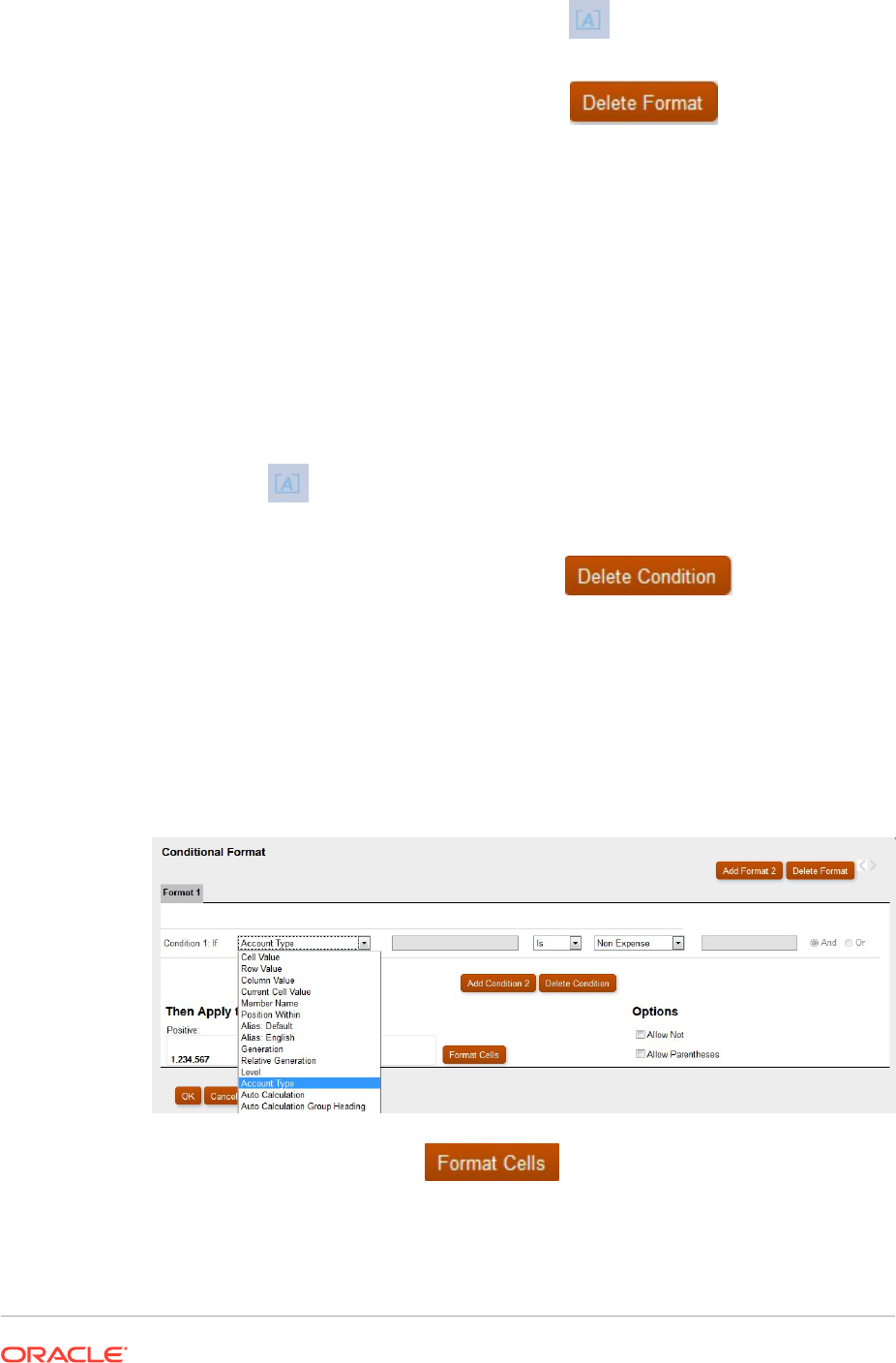
1. In a grid, select a cell or cells, and then click ; or, right-click a cell, then select
Format, and then Conditional Format.
2. In the Conditional Format, dialog box, click .
3. If there is more than one format, from the drop-down list, select the format to
delete.
4. Click OK to return to the grid.
Deleting Conditions
You can delete a condition if it is no longer applicable to the grid, cell, row, or column.
This functionality enables you to delete a single condition rather than an entire format,
which can hold as many as seven conditions.
To delete a condition:
1. In a grid, select a cell or cells, and then do one of the following:
• Click
.
• Right-click a cell, then select Format, and then Conditional Format.
2. In the Conditional Format dialog box, click .
3. If there is more than one condition, from the drop-down list, select the condition to
delete.
4. Click OK to return to the grid.
Conditional Formatting Example
From the Conditional Format dialog box, select Account Type in Condition 1: If.
Select Expense, and then click to apply bold formatting to the
selected cell. (Leave all other font properties unchanged.)
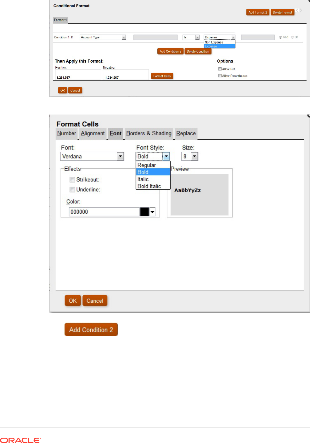
Click
to add a second condition. Set the Condition 2: If statement to
Current Cell Value. Set the operator value to > (greater than), leave the comparison value
set to Value, and set the numeric value to 1000.
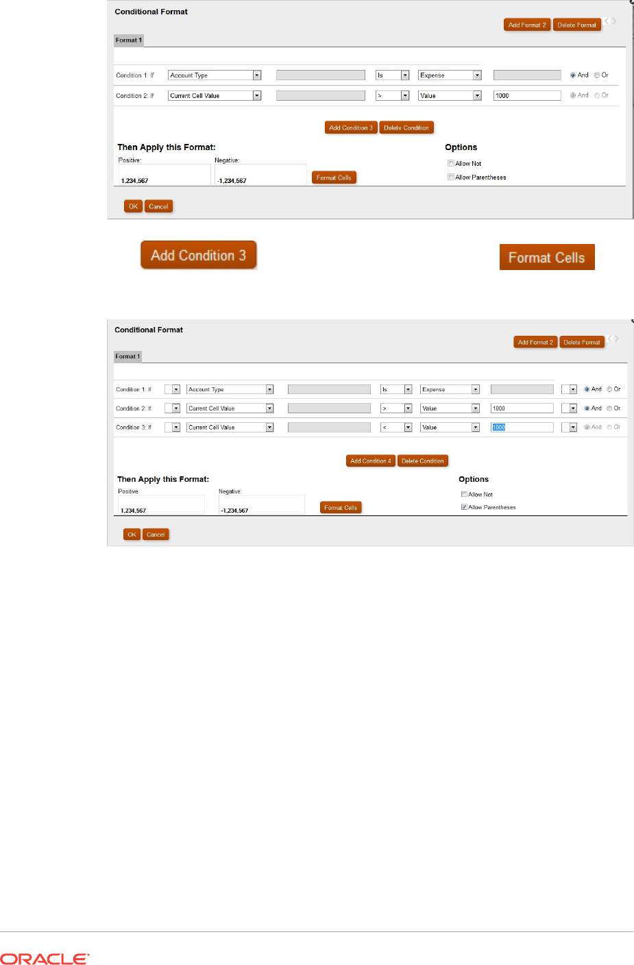
Click to add another condition, and then click to set
the background color to green when a Cola cell has a value < 1000.
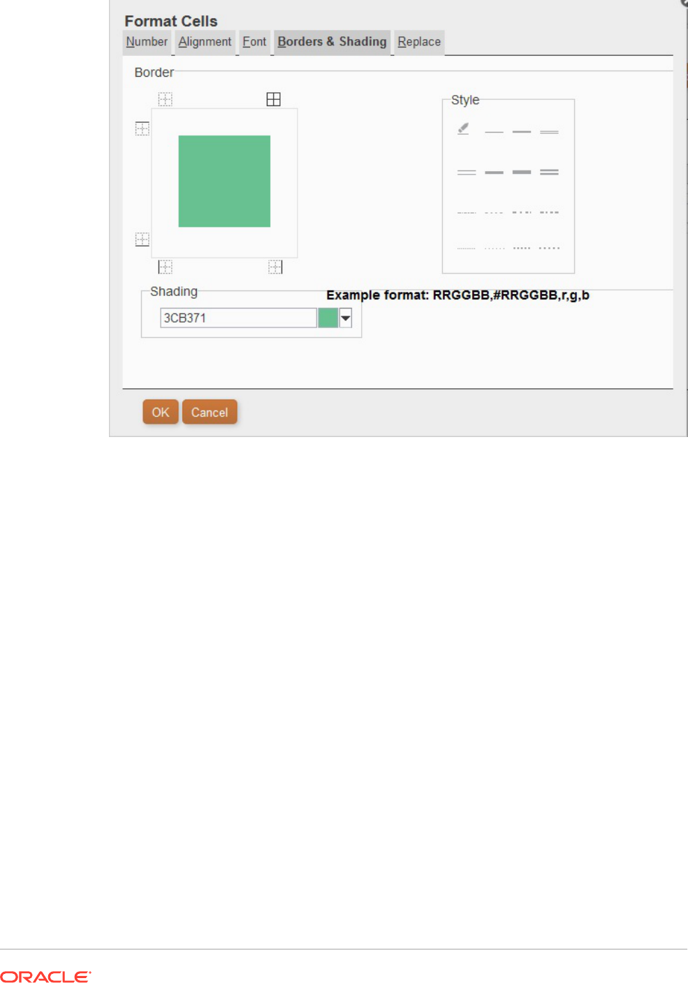
After you establish the conditions, you can select the check box for Allow Parentheses.
In the following scenario:
Condition 1 and Condition 3
or
Condition 2 and Condition 3
If a cell has the label Cola associated with it and the cell value < 1000, the background is set
to green. If a Member Name contains Cola and the cell value is < 1000, the background is set
to green.
Using Conditional Suppression
Use conditional suppression to suppress the display of rows, columns, or grids.
Related Topics
• About Conditional Suppression
• Conditional Suppression Behavior
• Defining Basic Conditional Suppression
• Defining Advanced Conditional Suppression
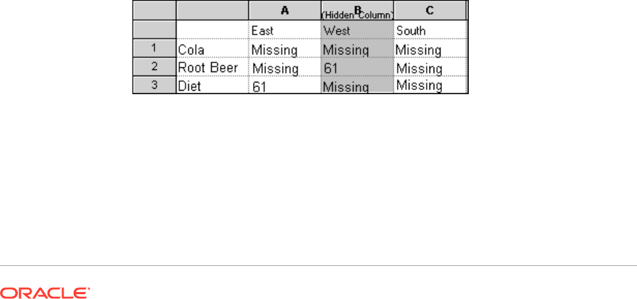
• Deleting Conditional Suppression
About Conditional Suppression
You can suppress the display of rows, columns, or grids using the following methods:
• Basic—Suppresses rows, columns, or grids based on "If Zero," "If Missing," and
"If Error". See Defining Basic Conditional Suppression.
• Advanced—Suppresses rows, columns, or grids based on several attributes. For
example, you can specify that if a row contains cells with values below 100, the
entire row is suppressed. See Defining Advanced Conditional Suppression.
Conditional Suppression Behavior
• If an entire row or column meets the criteria specified for conditional suppression,
the entire row or column is hidden; if only some of the cells in a row or column
meet the criteria specified for conditional suppression, the row or column is not
hidden.
• Suppressed data is not included in calculations. For example, if you suppress rows
23 and 24 and then calculate a sum for rows 10 through 30, the sum does not
include the values in rows 23 and 24.
• Conditional evaluation based on data values uses the underlying data value
retrieved from the data source, not a formatted data value that may appear
differently in the report.
For example if decimal places are not displayed in the report (for example 1,234),
the evaluation is based on the underlying data value (for example, 1,234.5678).
• When evaluating suppression, you can include or ignore the values and
calculations in hidden rows and columns. This option is enabled only when Hide
Always is selected for the row or column. Regardless of the setting selected, you
can evaluate suppression based on hidden cells when you specifically reference
the cells using the Advanced Option method for conditional suppression.
• Hidden cells are ignored when evaluating the suppression of a row or column
unless they are specifically referenced. The output of the report is based on the
condition used.
The following example is a report with hidden columns.
This report is used to describe the following conditional suppression scenarios.
In the following examples, column B is hidden, and rows 1, 2, and 3 are selected
for conditional suppression.
The first example shows the results when specifying suppression based on
missing data. Since the condition does not reference the hidden column or a
specific cell in the hidden column, the hidden column is ignored:
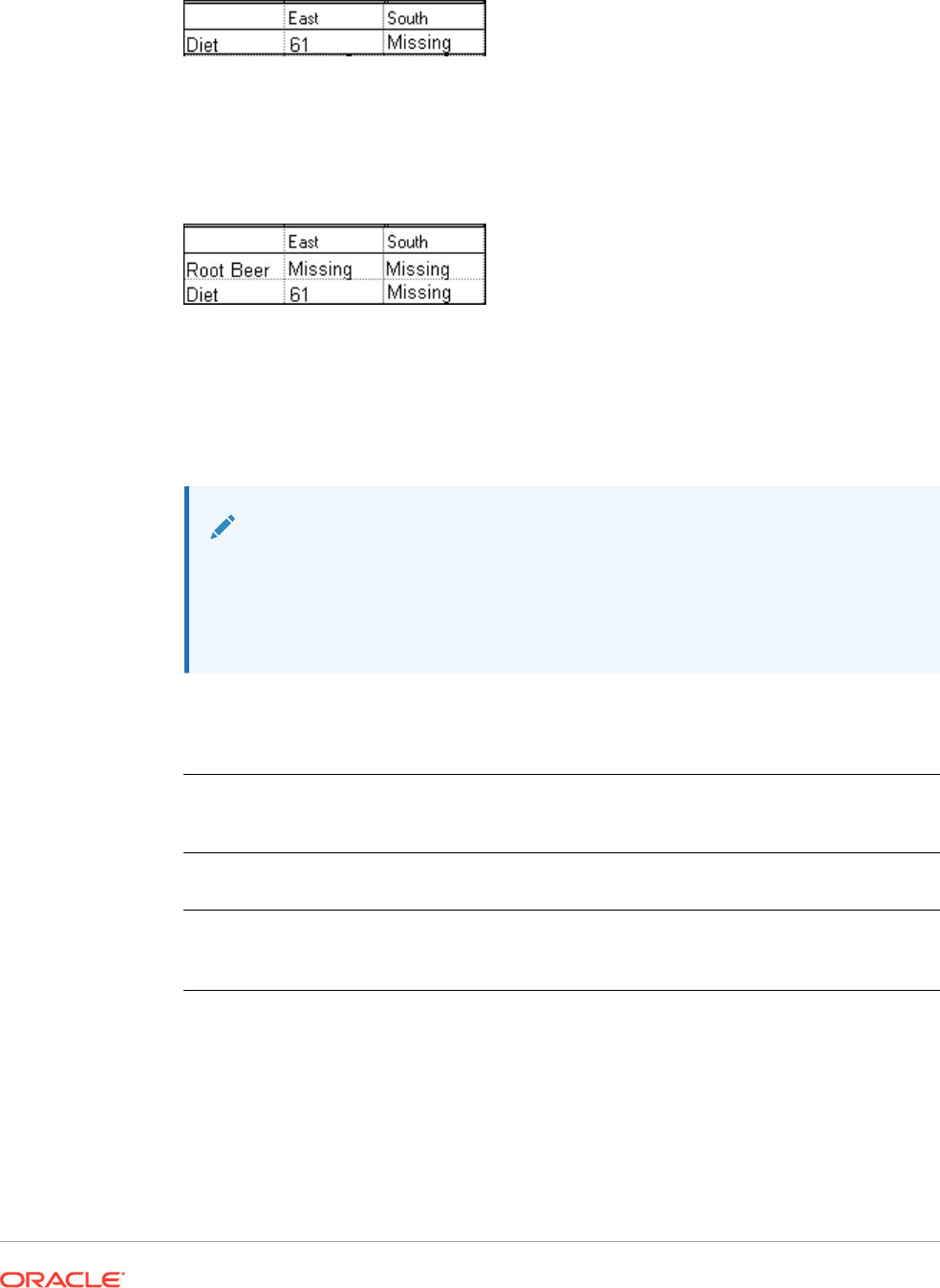
Suppress Row If: Data Values in Current Row = No Data
The second example shows the results when specifying suppression based on the data
cells in the hidden column B. Since the condition specifies the hidden column B, Root
Beer is not suppressed because cell B2 contains data:
Suppress Row If: Data Values in Column B = No Data
• When you use conditional suppression based on attributes, you can suppress formula
rows or columns based on the suppression status of other data rows or columns, and you
can suppress text rows or columns based on the suppression status of other rows and
columns. (You cannot suppress data rows or columns based on the values of formula
rows or columns.)
Note:
When suppressing text rows or columns based on the suppression status of
other rows or columns, in the text row or column properties, deselect Basic
Options suppression and select Advanced Options Setup to define
conditional suppression for the text row or column.
The following table describes whether suppression is valid when referencing another
suppressed data, formula, or text row or column.
If the Row / Column
Type you are
suppressing =
And if suppression is based on Row / Column of Type =
<row intentionally left
blank>
Data Formula Text
Data Available Available Not Available
Formula Available Not Available Not Available
Text Available Available Not Available
Defining Basic Conditional Suppression
Use basic conditional suppression to suppress data in rows or columns based on "If Zero," "If
Missing," and "If Error". You can combine basic conditional suppression with advanced
suppression options. See Defining Advanced Conditional Suppression.
To suppress data:

1. In a grid, select the rows or columns to suppress, or select the entire grid.
2. In Properties, under Suppression, select Basic Options, and the select one or
more of the following options:
• If Zero, Suppress—Hide rows or columns where all cell values equal zero.
• If Missing, Suppress—Hide rows or columns where all cells are empty.
• If Error, Suppress—Hide rows or columns where data cannot be retrieved or
calculated because of errors.
To replace
#ZERO
,
#MISSING
, or
#ERROR
values in rows or columns that cannot be
suppressed:
1. Select an entire grid by clicking in the upper left cell.
2. In Properties, expand Suppression, and then do one of the following.
• To replace zero (
#ZERO
) values in cells, enter a value in the Zero Values text
box.
• To replace no data (
#MISSING
) in cells, enter a value in the No Data text box.
• To replace erroneous data (
#ERROR
) in cells, enter a value in the Error text
box.
Defining Advanced Conditional Suppression
Use advanced conditional suppression to suppress rows or columns in a grid based on
specified attributes or values. Conditional suppression can be simple or complex, and
can contain a maximum of seven conditions. You can combine advanced conditional
suppression with basic suppression options. See Defining Basic Conditional
Suppression.
When you define conditions, you can include the Not operator to suppress rows or
columns that do not meet the condition (that result in false), and parenthesis to
enclose and separate conditions from other conditions. Conditional suppression may
be based on data or formula values.
To suppress data:
1. In a grid, select the rows or columns to suppress, or select the entire grid.
2. In Properties, under Suppression, select Advanced Options, and then click
.
3. In the Conditional Suppression, dialog box, define what to suppress:
a. For Suppress Row/Column: If, select a property value from the drop-down.
b. Depending on the property value you select, you may be able to enter a
reference value.
For example, if you select "Generation," then you can click the drop-down to
select a reference value of "Period," "Version," "Account," "Entity," "Product,"
"Year,", "HSP_View," or "Scenario." If you select "Value in Cell,", then A, 1 is
automatically filled in. You can change this value if desired.
c. Select a comparison operator.
• = (equal to)

• < > (less than or greater than)
• > (greater than)
• > (greater than)
• > = (greater than or equal to)
• < = (less than or equal to)
• equals (is equal to)
• not equals (is not equal to)
• starts with
• ends with
• contains
• is
d. Select a comparison option.
• Value—Returns the cell location; for example, A, 3.
• Cell Value—Returns the cell location; for example, A, 3.
• Row Value—Returns the number of the row.
• Column Value—Returns the letter of the column.
• Zero—Assigns zero value for condition.
• No Data/#MISSING—Indicates no data value for selection.
• Error—Assigns the condition as an error.
• String—Enables the definition of a string for the condition.
• 0, 1, 2—Indicates the number of levels or generations in the selected dimension.
Note: The options in the drop-down list depend on the property value you selected.
e. Depending on the comparison option you select, a reference value may be filled in.
You can type in a value, or click the drop-down to change the value if desired.
You can type in a value, or click the drop-down to change the value if desired. For
example, if you select "Cell Value, "then the reference value is automatically
populated with "A, 1." At this point, you can keep this value or type in a new value. If
you select "Generation," then the reference value is automatically populated with
"Period." At this point, you can keep this value, or click the drop-down to select a new
value.
4. Optional. In the Options area, add one of the following logic options to your condition:
• Allow Not—Allow suppression only if the condition is not met.
• Allow Parentheses—Define precedence, or order of consideration for conditions,
and specify the set of conditions as intended.
5. Optional. Click to add additional conditions.
You can add up to seven conditions.
If you add additional conditions, select And to combine a condition with the next
condition, or select Or to distinguish a condition from the next condition.
6. Click OK to return to the grid.

Note that the Conditional Suppression dialog box displays one of the following labels
above the suppression options:
• Basic Options:None—Basic options not selected with Advanced options.
• If Zero, Suppress OR—If Zero is selected with Advanced options.
• If Zero OR Missing, Suppress OR—If Zero and If Missing are selected with
Advanced options.
• If Zero OR Error, Suppress OR—If Zero and If Error are selected with Advanced
options.
• If Zero OR Missing OR Error, Suppress OR—If Zero, If Missing and If Error are
selected with Advanced options.
• If Missing, Suppress OR—If Missing is selected with Advanced options.
• If Missing OR Error, Suppress OR—If Missing and If Error are selected with
Advanced options.
• If Error, Suppress OR—If Error is selected with Advanced options.
Deleting Conditional Suppression
You can delete conditional suppression if it is no longer applicable. This functionality
enables you to delete one condition at a time, which can hold as many as seven
conditions.
To delete conditional suppression:
1. In a grid, select the rows columns to which conditional suppression is applied.
2. In Properties, under Suppression, click
.
3. In the Conditional Suppression dialog box, click , and then
select the condition to delete.
4. Delete additional conditions if desired, and then click OK.
Providing For Detailed Data and
Documents in Reports
Related Topics
• Setting Up Expansions to Access Detailed Data in Reports
You can design a report to display detail rows and columns of a grid at the request
of a user.
• Positioning Expansion Rows and Columns
You can specify whether expanded items are displayed before or after the
dimension’s summary-level row or column.
• Working With Related Content
Related content allows designers to set up links to Financial Reporting documents
and custom URL links.

• Attaching Cell Documents in a Report
Cell documents that are attached at the data source can be accessed in reports.
• Printing a List of Attached Cell Documents
Use the
ListofCellDocuments
text function to print a list of all cell documents and
attributes, such as description and start page number, that are retrieved in the report.
• Using Smart View
Oracle Smart View for Office provides a common Microsoft Office interface for Financial
Reporting.
Setting Up Expansions to Access Detailed Data in Reports
You can design a report to display detail rows and columns of a grid at the request of a user.
You do this by enabling the expansion of a dimension that has parent-child relationships
among its members. For example, if you enable the Time dimension to expand, users can
expand a row that displays quarters into months.
You access detail rows and columns by selecting summary rows and columns from reports
that are displayed.
To set up expansions to access detailed data in a report:
1. Open a report and select a grid.
2. Select the row or column headings for which you want to enable expansion.
3. In Heading Row Properties or Heading Column Properties, select Allow Expansion.
Positioning Expansion Rows and Columns
You can specify whether expanded items are displayed before or after the dimension’s
summary-level row or column.
To position expansion rows and columns:
1. Open a report and select a grid.
2. In Grid Properties, expand Position.
3. In Position of Expansions, select an option:
• Before Parent—Displays expansions before the summary-level row or column.
• After Parent—Displays expansions after the summary-level row or column. (This is
the default.)
Working With Related Content
Related content allows designers to set up links to Financial Reporting documents and
custom URL links.
Related Topics
• About Related Content
• Creating a Link to Related Content
• Modifying the Properties For Related Content

• Specifying Related Content Link Descriptions
• Examples of Related Content Results When Specified in Grid Cells
• Removing Access to Related Content
• Changing the Related Content Server for Multiple Reports or Grids in the
Repository
About Related Content
Related content allows designers to set up links to Financial Reporting documents and
custom URL links. A user, when viewing a report in HTML in the Explore Repository,
can drill into a related content link and execute the linked report or URL. Related
content is supported in dynamic and snapshot reports and books.
When applying related content, keep in mind these points:
• When you run a report in the Explore Repository, the HTML Viewer displays the
related content cells with an underline. If you click the link, a Related Content
dialog box is displayed where you can select the desired target object to launch.
• You can specify related content for any cell within a grid object (data cells, text
cells, formula cells, heading cells), text object, image object or chart object. When
related content is any cell except a text cell, the point of view (POV) included in the
related content link is limited to the unambiguous members for that cell. For
examples of related content results in a grid, see Examples of Related Content
Results When Specified in Grid Cells.
• You can specify related content conditionally in the Conditional Format dialog box
on any grid object cell. On the Replace tab of the Format Cells dialog box, you can
specify related content links. For example you can enter a condition: if Market
member name is "East", link to ReportABC; if Market member name is "West", link
to ReportXYZ. See Applying Conditional Formatting.
• You can specify related content on Image, Chart and Text objects. The link is
applied to the entire object. You can click Chart and Image objects with related
content to point to the related content link. For Text objects with related content,
the entire textual content is marked as a hyperlink. When clicked, the related
content link is followed.
• When a data cell has a related content link because of a cell document, if that cell
is referenced through the <<GetCell()>> or <<CellText()>> function, the
<<GetCell()>> or <<CellText()>> value also has the related content link. The
behavior of a related content link in a cell document is the same as a related
content link designed in a Financial Reporting report. For more information about
<<CellText()>>, see CellText.
• URL strings in Text objects and Grid object text cells are replaced with a "[Link]"
hyperlink to that URL. URLs must begin with "http", "https", or "ftp" in order for a
URL to be converted. For example, if you type "
This is a link to Google
http://www.google.com
" the result is "
This is a link to Google [Link]
".
Text object and Grid object text cells are evaluated after any <<CellText()>> and
<<Annotation()>> functions are evaluated. So if cell text or annotation function
contains URLs, they are processed into hyperlinks as appropriate.
• When you select related content for a grid, you can also specify dimension
descriptions for the related content link dimensions. The textual information is
displayed in the book Table of Contents and navigation path (breadcrumb). The
description is defined using the <<Value()>> function in the Add Related Content dialog
box. See Modifying the Properties For Related Content.
• When using related content in a report, the point of view (POV) of the report is set to that
of the selected cell. For example, if you select the Gross Margin row of the Canada
column, the POV for the account is set to Gross Margin, and the POV for the entity is set
to Canada before the linked report is displayed. The POV context is not passed when you
link to books through related content.
• You can define related content for data cells within a row or column. You can specify the
same report for a group of cells by selecting the desired cells in the grid and then defining
the related content. Based on the type of related content selected, you can modify
properties, such as their label and URL and default display options.
• Object-level security is not enforced when you select related content, which enables you
to select any report among the entire contents of each repository. However, object-level
security is enforced when the report is requested for viewing.
Creating a Link to Related Content
To create a link to related content:
1. In a grid, select the desired rows, columns, cell object, grid, chart, image or text object.
2. From the Property sheet, select the Add Related Content check box, and then click
.
3. In the Add Related Content dialog box, click under the Oracle Hyperion Reporting
and Analysis node to expand the available folders.
4. Select the folders and reports to which you want to create links:
• Select folders to enable end users to select from the complete contents of the folder.
To select a folder, select the folder, and then click to move the folder to the list
of selected folders and reports.
• To select an individual report, expand the folder that contains the report, then select
the report, and then click to move the report to the list of selected folders and
reports.
5. Optional. Modify the properties of the folders and reports selected for related content.
You can modify the properties of folders and reports in one of the following ways:
• Select the check box next to Show Properties dialog when adding content from
Oracle Hyperion Reporting and Analysis data sources check box.
After you select a folder or report to link and click , the Related Content
Properties dialog box is displayed.
• Highlight the folder or report in the list of selected folders and reports, and then click
to display the Related Content Properties dialog box.
See Modifying the Properties For Related Content.
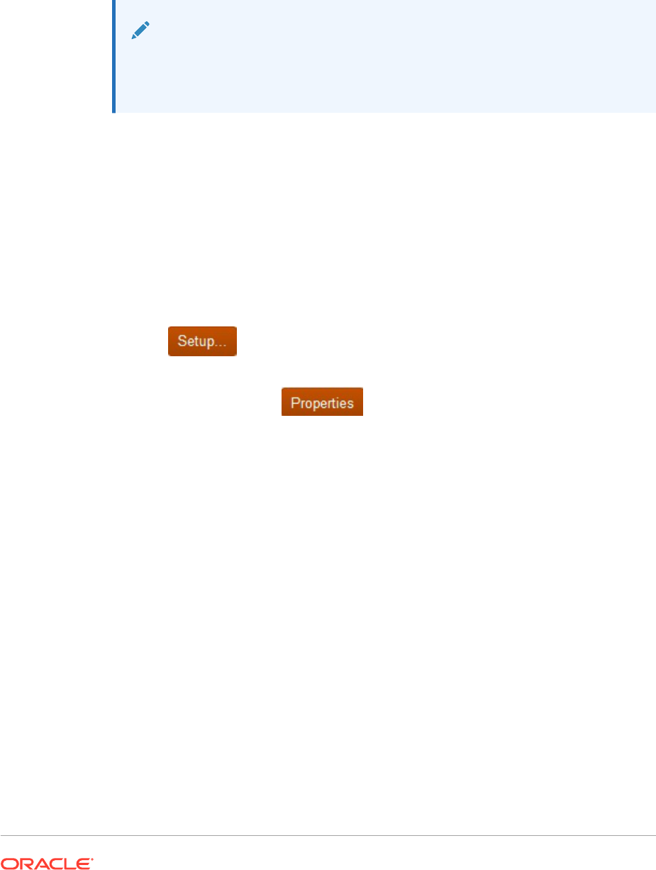
6. Optional. Select Show all object types to see all repository object types in the
Add Related Content dialog box.
When this option is not selected, only Financial Reporting objects are shown.
Showing all object types simplifies book functionality
7. Click OK.
Note:
When related content has been added to a cell, image, chart, or text, a red
indicator is displayed in the top right corner of the cell to indicate that it has
related content.
Modifying the Properties For Related Content
You can modify properties of a selected report object. Based on the type of report
object selected, you can modify such properties such as its label or URL, and you can
set default display options.
To modify properties for related content:
1. In a grid, select the rows, columns, or data cells that contain the related content
item to edit.
2. From the Property sheet, select the Add Related Content check box, and then
click
.
3. In the Add Related Content dialog box, select a report object selected for related
content, and then click .
4. In the Related Content Properties dialog box, edit the desired properties:
The items that are displayed depend on the report type selected. For example, for
Financial Reporting, all display options are provided for a report, snapshot, book,
and snapshot book. However, for a custom link, only the label and a URL fields are
available.
Depending on the report type, the following items are available to edit:
• Label— Name of the report object link. You can apply the
<<Value()>>
text
function to specify descriptions of the dimension values for the related content
link. See Specifying Related Content Link Descriptions.
• URL Tabs—URL of the linked object.
• Display Options—For Provide, select the formats that can be viewed by the
end user (HTML and PDF). For Default , select the format to link with the
report name as the primary selection. The format not selected is listed as the
secondary selection.
5. Click OK.
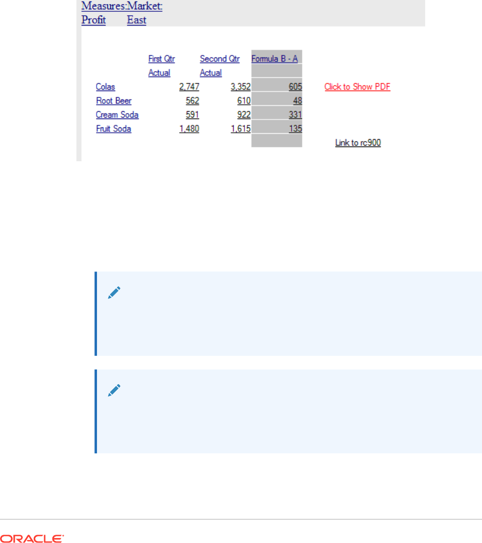
Specifying Related Content Link Descriptions
In HTML output of a book, you may want to see the description of the related content results
in the table of contents and navigation path (breadcrumb). In the Label field of the Related
Content Properties dialog box , you can include a text function, <<Value()>> , to specify the
related content result you want shown. Using the image below as an example, where you
have Measure and Market on the POV, Product on the rows (showing aliases), Year (with
custom heading text) on the first column, and Scenario on the second column of a report
result, if the description of the related content link is
rc900<<Value(Product)>><<Value(Year)>><<Value(Market)>>
the following will show in
related content results of the book's table of contents and navigation path:
• If you click on cell 3,B (value of 922), the text displayed is:
rc900 CreamSoda, Second
Qtr, East.
• If you click on cell 1,A (value of 2,747), the text displayed is:
rc900 Colas, First Qtr,
East
.
• If you click on the "Fruit Soda" heading cell, the text displayed is:
rc900 Fruit Soda,
East
(Year is not included since it is ambiguous).
Note:
The heading value of the appropriate dimension is shown, not necessarily the
member name. For example, "Cola" is shown rather than "100", and "First Qtr"
is shown rather than "Qtr1".
Note:
If the dimension specified in the <<Value()>> function is not included in the POV
of the related content link, the <<Value()>> text is replaced with an empty string
(" ").
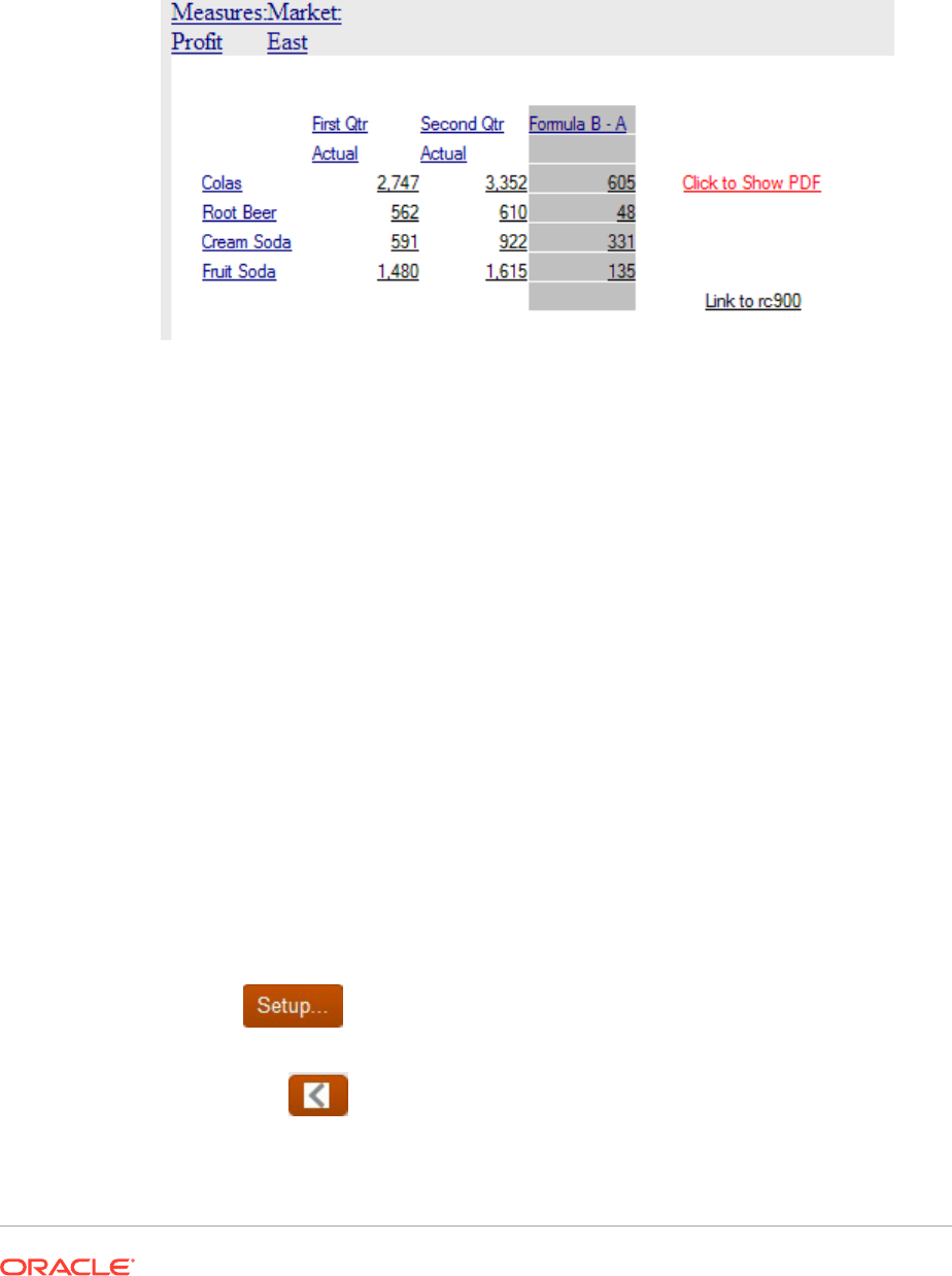
Examples of Related Content Results When Specified in Grid Cells
The following report image has related content on all cells. Measure and Market are on
the point of view (POV), Product aliases are on the rows, Year and Scenario are on
column 1 and 2. Column 3 is a formula column and column 4 is a text column.
• If you execute related content on the row headings (Colas, Root Beer, Cream
Soda, and Fruit Soda), the POV included in the related content link includes all the
dimensions except Year and Scenario. You cannot specify a Year or Scenario
member when clicking on the row heading since it is ambiguous which member
you want.
• If you execute related content from the formula cells, Product, Measures and
Market are included; Year and Scenario are not included.
• If you execute related content from the formula heading cell (Formula B-A), only
Measure and Market from the POV are included.
• If you execute related content from the "Link to rc900" text cell, only Measure and
Market from the POV are included.
• If you execute related content from the "Click to Show PDF" text cell, Product,
Measures, and Market are included; Year and Scenario are not included.
Removing Access to Related Content
To remove access to a linked report:
1. Select a report that contains links to related content.
2. Select the rows, columns, or data cells from which you want to remove a related
content link.
3. From the Property sheet, select the Add Related Content check box, and then
click
.
4. In the Add Related Content dialog box, highlight the report object to remove, and
then click .
5. Click OK.

Changing the Related Content Server for Multiple Reports or Grids in the
Repository
After moving content from another server, you can use Planning and Budgeting Cloud
Workspace to change the server for selected reports, grids, or both in the repository by
specifying a new URL or a substitution variable. You may want to change the related content
servers; for example, you might do this when moving your reports and grids from a
development server to a production server.
Attaching Cell Documents in a Report
Cell documents that are attached at the data source can be accessed in reports.
Related Topics
• About Attaching Cell Documents in a Report
• Supported Microsoft Office File Types
• Viewing Reports Containing Cell Documents
• Displaying a List of Cell Document
About Attaching Cell Documents in a Report
Cell documents that are attached at the data source can be accessed in reports. The
attached documents appear as hyperlinks at the end of a PDF or snapshot report. The
documents are accessed in the HTML client when drilling into a cell. In addition, you can
insert footnotes into a text object or text cell of the report that lists information about the
attached cell documents by selecting the ListofCellDocuments text function. All cell
documents have a point of view associated with the data cell to which they are attached.
A data cell can contain multiple cell documents. If a data cell contains cell documents in the
data source, a designer can extract those documents, based on the given cell’s POV. Cell
documents can be attached to reports contained in books and snapshot books.
To attach cell documents:
1. Select a data type cell in a grid.
2. In Cell Properties, select Retrieve Cell Documents.
For optimum retrieval performance, select Retrieve Cell Documents only for cells with
attachments to include in the report. If cell documents exist for the selected cell, they are
appended to the report when printed.
When you attach cell documents in a report, consider the following points:
• Include the correct supported extensions for files.
• Files which are corrupt or improperly uploaded to the ADM provider will not print.
• Documents containing file extensions that are not properly registered to print will fail.
• Financial Reporting Web Studio does not support Microsoft files containing macros or
that trigger UI components requiring user input. Some Microsoft files with macros perform
operations when the file is opened which include the launching of dialogs requiring user

input. Files that display dialogs or UI components requiring user input may not be
available to print.
This may also hold up the completion of the PDF generation process. The server’s
administrator may need to stop the application through Task Manager to resume
printing activities. Because the application is launched under the SYSTEM
account, it may not be visible since the process was not initiated by the login
account.
Supported Microsoft Office File Types
• Microsoft Word files (*.doc, *.docx, *.rtf)
• Microsoft Excel files (*.xls, *.xlsx)
• Microsoft PowerPoint files (*.ppt, *.pptx)
• PDF files (*.pdf)
• Text files (*.txt)
Viewing Reports Containing Cell Documents
In Planning and Budgeting Cloud Workspace, you can view reports containing cell
documents in PDF or HTML output.
PDF Output
• Hyperlinks to all files are included in the bottom of the document output, after the
Financial Reporting report content. Click a hyperlink to launch the document.
• The function returns the file name and description parameters for all cell
documents. The page number parameter is only displayed for the supported
Microsoft Office documents.
HTML Output
• All cell documents in HTML preview are hyperlinks.
• Depending on the user settings in the browser, the cell document may be opened
automatically in a new browser window.
• The ListofCellDocuments function returns the file name and description
parameters, but not the page number parameter.
Displaying a List of Cell Document
Use the ListofCellDocuments text function to display a list of all cell documents and
attributes such as description and start page number that are retrieved in the report.
You can enter the function in a text object, text cell, or text cell heading.
Printing a List of Attached Cell Documents
Use the
ListofCellDocuments
text function to print a list of all cell documents and
attributes, such as description and start page number, that are retrieved in the report.
You can enter the ListofCellDocuments into a text object, text cell, or text cell heading.
Using Smart View
Oracle Smart View for Office provides a common Microsoft Office interface for Financial
Reporting.
The centralized interface enables simultaneous use of multiple Oracle products, and
improves integration with Microsoft Office. The Smart View implementation provides the
following functionality:
• Exports the current page of the current data object to Excel, Word, or PowerPoint
• Notifies you when you can upgrade to new releases of Smart View.
Previewing and Printing Reports
Related Topics
• Previewing Reports
You can preview reports in a web browser.
• Responding to Prompts When Previewing
If a report is designed with prompts, those prompts are displayed when you preview the
report.
• Printing Tips for Designers
When printing reports consider positioning and alignment, how to print text boxes and
grids, printing page dimension headings, and printing headers and footers.
Previewing Reports
You can preview reports in a web browser.
1. Open a report in the Report Designer.
2. Do one of the following:
• Click
or .
• Select File, and then either HTML Preview or PDF Preview.
Note:
A popup blocker warning may be displayed after previewing the report several
times. Click the popup blocker warning dialog box and choose to allow the popups
to continue previewing the report.

Note:
When previewing Financial Reporting reports or books in Chrome, complete
the following steps:
1. Click , and then select Settings.
2. Scroll down and open Advanced settings.
3. Expand Content Settings.
4. Expand PDF documents.
5. Enable the Download PDF files instead of automatically opening
them in Chrome setting.
Responding to Prompts When Previewing
If a report is designed with prompts, those prompts are displayed when you preview
the report.
You must respond to the prompt and provide the requested information by selecting
members from the prompt list. You can also edit the prompts manually. If the prompts
contain alias names, you can edit the alias names by converting to member names.
See Setting Up Report Prompts.
To respond to a prompt when previewing a report:
1. With a report open in the Report Designer, select File, and then either HTML
Preview or PDF Preview.
2. In the Respond to Prompts dialog box, under the Selection column, do one of
the following:
• If the member is known, enter the member name in the text box for the
respective prompt.
If the text box is disabled, the prompt contains alias names. To edit the text
box, select Edit Member Names. If multiple members are provided for the
prompt, separate the members with commas.
Selecting Edit Member Names displays member names in the text box, not
alias names. You can edit the member name associated with an alias.
• Click
.
In the Select Members dialog box, the default member is listed in the
Selected area. Click and to move members between the panels.
For more information on defining members, see Defining Members,
3. Select OK, and then click Run.
Note: After running a report multiple times in succession, you may see a pop up
blocker warning in the browser. If this occurs, click on the warning and choose to allow
the pop ups.
Printing Tips for Designers
When printing reports consider positioning and alignment, how to print text boxes and grids,
printing page dimension headings, and printing headers and footers.
Related Topics
• Positioning and Alignment
• Printing Text Boxes
• Printing Grids
• Printing Page Dimension Headings
• Printing Headers and Footers
Positioning and Alignment
Setting relative positioning on auto-sized report objects gives you precise control over how
report objects are positioned relative to one another. If none of the report objects in your
report is auto-sized, then the relative positioning is ignored.
If you set the position of a report object to relative, all report objects within the design shift so
that the distance between the auto-sized report object and fixed report objects remain the
same.
For example, if Grid A is auto-sized and has horizontal positioning set to "center", then Grid A
is printed in the center of the page. If Chart A is linked to Grid A and has its vertical position
set to "relative," then Chart A is printed one inch (25.4 mm) from the bottom edge of Grid A.
If the alignment for Chart A is not set to relative, it is printed on the absolute coordinates in
the layout of the grid, so it might overwrite Grid A.
Note:
Vertical and horizontal positioning are not maintained after changes are made to the
report.
Note:
When printing reports containing overlapping objects, objects may not print as
displayed in the designer, requiring you to rearrange the objects in your report.
Printing Text Boxes
If you set the auto-size property for a text box:
• when you print a report, the height of a text box increases or decreases to accommodate
all the text in the text box.
• The width of the text box does not change.

If the auto-size property is not set when you print a report:
• The text box is printed at the height and width of the grid.
• Text that does not fit in the text box is truncated.
Printing Grids
If you set the auto-size property for a grid and then print the grid, the height and width
of the grid increases or decreases to accommodate all data in the grid.
When the auto-size property is not set, the grid prints at the height and width specified.
If a row or column does not fit on a page, it prints on subsequent pages. The columns
printfirst using as many pages as needed, followed by the rows.
You use the positioning properties of the grid to align the grid on the page. Manually
positioning the grid to the right or bottom of the page does not ensure that the grid will
print on the right or bottom of the report.
When a grid is set to auto-size, and does not fit on one page, it prints on subsequent
pages. The columns print first, starting on the left margin of the next page, followed by
the rows, which print starting at the top of the next page.
Printing Page Dimension Headings
You can specify a page dimension heading for a grid in Page Properties. When you
print a report, the page dimension heading prints every time the page member
changes.
Page dimension headings print as follows:
• The text is left justified at the left edge of the grid.
• The text is auto-sized vertically, and the width is set to the width of the grid.
• The heading prints above the first row in the grid each time the page member
changes.
A page dimension heading prints the member name every time the page member
changes. Members on the page dimension can have their own custom heading.
To define a page dimension heading:
1. Open a report and select a grid.
2. Select the Pages list box on the grid.
3. In Page Properties, under Page Printing Positioning, select an option for the
heading.
• New Page - Top—Prints a new page at the top of the next page.
Use this option when a chart is linked to a grid and you want to ensure that the
chart and grid print next to each other every time the page member changes.
• New Page - Same—Prints a new page at the specified grid location.
Use this option in the following situations:
– The grid has horizontal or vertical alignment properties set, and you want
the grid to print in the same position on each page. For example, if you set
the grid position to Center/Middle, it prints in the center of each page.

– When a chart is linked to a grid, and you want to ensure that the chart and grid
print next to each other whenever the page member changes.
• Same Page—Prints the new page immediately after the data from the previous page.
Note:
If a chart is linked to a grid, the chart prints once; not every time the page
member changes.
Printing Headers and Footers
When printing header and footers, keep in mind the following points:
• You can place an auto-sized text box in the header; however, if the text box height
expands beyond the header, it prints beyond the header boundary.
• You can place an auto-sized text box in the footer; however, if the text box height
expands beyond the footer, the text is truncated.
• If you place an object near the top or bottom of the page, it might overlap the header or
the footer.
Saving Reports
To save a report to the repository:
1. With the report displayed in the layout area, select File, and then Save.
2. In the Save Report dialog box, select a folder or create a new folder in which to save the
report.
3. In Name, enter the report name.
You can use upper and lowercase letters, spaces and numbers. You cannot use the
following characters: %,?,+,<,>,|,@,#,$,^,&,*.
4. In Description, enter a description of the report.
5. In Type, select either Reports or Snapshot Reports.
When you save a report as a snapshot report, the report is converted to a snapshot
containing static data for that period of time. Any time a snapshot report is viewed, data-
level security does not apply. Data-level security is applied when the snapshot report is
created and is based upon the data level security that is set up for the user who saved
the snapshot report.
6. Click Save.
Using Functions
Related Topics
• Mathematical Functions
Mathematical functions perform calculations on numeric values or data from a grid.

• Text Functions
Text functions return report information, such as the report name or the report
description.
• Conditional Functions
When creating an If, Then, If conditional function, you can use conditional
operators and complex conditions.
• Financial Functions
Financial functions include
Rank
,
Variance/Var
, and
VariancePercent/
VarPercent
.
Mathematical Functions
Mathematical functions perform calculations on numeric values or data from a grid.
Related Topics
• About Mathematical Functions
• Abs
• Average
• AverageA
• Count
• CountA
• Difference
• Eval
• Max
• Min
• PercentofTotal
• Product
• Round
• Sum
• Truncate/Truc
About Mathematical Functions
Mathematical functions perform calculations on numeric values or data from a grid.
Mathematical functions, formulas, and their syntax are not case-sensitive.
The syntax for a mathematical function is:
FunctionName(arguments)
where:
FunctionName
is the name of the mathematical function.
arguments
are a numeric value, a row, column, or cell reference, or an embedded
function.

Arguments in Mathematical Functions
Related Topics
• Numeric Arguments
• Row, Column, or Cell Reference Arguments
• Aggregate Property Arguments
• Reference Property Arguments
• Embedded Functions as Arguments
Numeric Arguments
The syntax for a numeric argument is:
(numeral1, numeral2,...numeraln)
where numerals 1 through n are any numbers including decimals and negative values. For
example, the expression
Average(10,20,30)
returns the value 20.
Row, Column, or Cell Reference Arguments
The syntax for a row, column, or cell argument is:
FunctionName(GridName.GridElement[segment(range)].Property)
Table 7 Argument Components
Argument Description
GridName
(Optional) Name of a grid.
For example,
Difference (grid1.row[5], grid2.row[5])
returns the
difference of two rows on grid1 and grid2.
If
GridName
is not specified, the default is the current grid where the formula is
entered.
GridElement
(Optional) One of the following keywords:
row
,
col
,
column
, or
cell
.
For example,
Max(row[1], row[2], row[3])
returns the maximum value of
three rows. (The keyword
row
and
column
or
col
is optional.)
You must specify row and column segment IDs. For example,
cell[2, A]
refers
to the cell that is the intersection between row 2 and column A.
The keyword
cell
is optional. For example,
[5,B]
refers to the cell that is the
intersection between row 5 and column B. Cell references can use
[row, col]
syntax or
[col, row]
syntax.
If
GridElement
is specified, letters represent columns and numbers represent
rows; for example,
Max ([1,A], [2,A], [3,A])
segment
(Required) Row, column, or cell reference number of a grid. For an expanded row
or column, you must specify the segment. For example,
row[2]
addresses row
segment 2. Segments are enclosed in square brackets [ ].
Table 7 (Cont.) Argument Components
Argument Description
range
(Optional) Rows, columns, or cells that are expanded from the specified segment.
If
range
is specified, the formula is calculated using only the specified range. For
example,
row[2(3:5)]
uses only the 3rd through 5th rows of expanded segment
2.
When
range
is not provided, all expanded cells are used.
Note:
If a segment expands to only one row or column, do
not use the
range
argument.
property
(Optional) One of the following keywords:
average
,
averageA
,
count
,
countA
,
max
,
min
,
product
, or
sum
. Property is used to aggregate the expanded rows,
columns, or cells specified.
Do not specify property when a reference is an argument. By not specifying
property, the function calculates the reference in the most appropriate way. For
example, the following expression returns the average of the cells within rows 1
and 2:
Average(row[1], row[2])
Whereas the following example first calculates the average of
row[1]
, then the
average of
row[2]
, adds these two results, then divides by 2:
Average(row[1].average, row[2].average)
The default property for a row, column, or cell reference that is not used as a
function argument is the
sum
property. For example, the following expression’s
default property is sum:
row[2]
See Aggregate Property Arguments and Reference Property Arguments.
Because
segment
is the only required part of a reference, the following references are
the same:
Grid1.row[1].sum
[1]
AverageA
and
CountA
include
#missing
and
#error
cells in the calculation. For
example, if row 1 is a segment row that expands to Qtr1 = 100, Qtr2 = 200, Qtr3 =
#missing, and Qtr4 = 400, the following function returns the value four (4):
row[1].CountA

All other functions exclude
#missing
data or
#error
cells. For example, the previous example
of row 1 that expands to Qtr1 = 100, Qtr2 = 200, Qtr3 = #missing, and Qtr4 = 400, returns
three in this example:
row[1].Count
Aggregate Property Arguments
An aggregate row, column, or cell contains multiple rows, columns, or cells, respectively.The
aggregate property argument is the last argument in the following mathematical function
syntax:
FunctionName(GridName.Gridelement[segment(range)].property)
You apply aggregate properties to a row, column, or cell reference. Aggregate properties
include:
• Average
• AverageA
• CountA
• Max
• Min
• Product
• Sum
When used as a mathematical function argument, the default for property is the same as the
function. In the following example the default property is
Average
:
Average(row[2])
When not used as a mathematical function argument, the default for property is
sum
. In the
following example the default property is the sum of an aggregate row:
row[2]
Reference Property Arguments
A reference property argument specifies how to treat formula reference results and is used in
conjunction with the other properties.
There is one reference property argument:
IfNonNumber/IFFN
.
IfNonNumber
specifies a replacement for
#Missing
and
#Error
values with a specific numeric
value.
The syntax is:
AXIS[segment(range)].IfNonNumber(arg).AggregateProperty
Table 8 Argument Components
Argument Description
AXIS
(Optional) A row, column, or cell keyword.
Segment(range)
Any axis reference, such as a row number or column letter.
IfNonNumber
How to treat missing or error data within the
AxisRef.
(arg)
What number to use if missing or error data is encountered within the
AxisRef
.
AggregateProper
ty
(Optional) The aggregate function used for aggregate segments. See
Aggregate Property Arguments.
For example:
If cell[1,A] = 3 and cell[1,B] = #Missing,
The following expression returns #Error:
cell[1,A] / cell[1,B]
The following expression replaces cell[1,B] with 1 and returns 3:
cell[1,A] / cell[1,B].ifNonnumber(1)
Note:
If you use suppression for
#Missing
or
#Error
in a grid, and the grid contains
a formula row or column that uses the
IfNonNumber
property,
#Missing
and
#Error
remain suppressed.
Embedded Functions as Arguments
You can embed functions as arguments within a function. In the following example, the
function
Average
is embedded in the function
Sum
:
sum(row[3:5], avg(row[4:6], 40, 50), row[7; 9], 70, 80)
• Row segments 3, 4 and 5
• The average of row segments 4, 5 and 6, with the numbers 40 and 50
• Row segments 7 and 9
• The numbers 70 and 80
Mathematical Operators in Expressions
Operators are symbols that perform arithmetical tasks or comparisons, or refer to
ranges of columns, rows, or cells. Use operators in formulas that perform calculations
on data rows or columns.
Table 9 Operators in Standard Formulas
Type Operator Description Example
Arithmetical + Add Add the values in rows 4
and 5.
[4] + [5]
A space is needed after + .
• Incorrect: 5+4
• Correct: 5+ 4
• Correct: 5+ -4
Arithmetical - Subtract Subtract 3 from the values
in row 4.
[4]- 3
.
A space is needed after - .
• Incorrect: 5-4
• Correct: 5 - 4
• Correct: 5 - -4
Arithmetical * Multiply Multiply the absolute values
in row 4 by 150.
Abs([4])* 150
Arithmetical / Divide Divide the values in row 4
by the values in row 5.
[4] / [5]
Arithmetical % Percentage Add the values in row 4
and multiply it by 10.
row[4].Sum*10%
Arithmetical ^ Exponential Return the sixth exponent
of row 4.
[4]^6
Arithmetical Decimal Decimal number Multiply the values in row 4
by 5.67.
[4] * 5.67
Reference [] Specifies a row, column, or
cell in a grid. Use numbers
for rows and letters for
columns.
Add the values in rows 4
and 12.
Sum ([4],[12])
Unary minus - Changes the sign of a
value
Divide the values in column
4 by 12 and change the
sign of the result.
([4] / 12)
Tip:
Use the
Eval
function to perform arithmetic operations as part of a function
parameter. See Eval.
Tip:
Natural precedence determines the order to carry out operations in
expressions with multiple operators. See Natural Precedence.
Mathematical Operands in Expressions
Operands specify the values that an operator uses to produce a result.
Table 10 Operands Supported in Financial Reporting Web Studio
Operand Examples
Literal 3, 0.0, 27.5, 65.334, -841
Row or column
reference number
[1], [4], [8], [A], [C:D]
Cell reference number [2, E], [E, 2]
Note:
This cell reference addresses row 2
column E.
Functions Average, Min, Max
Scoping Grid1.row[3]
In the following row formula, which multiplies the values in row 3 by 100, the row
reference [3] and 100 are both operands:
[3] * 100
Natural Precedence
If a standard formula has two or more operators, the system performs the operations
in the order of the operators' natural precedence.
The order of natural precedence to perform operations in an expression that has
multiple operators is:
1. Unary minus (-# where # is any number)
Do not add a space after the unary minus operator.
2. Multiplication (*) and division (/)
3. Subtraction (- #) and addition (+ # where # is any number)
Add a space after the subtraction and addition operator.
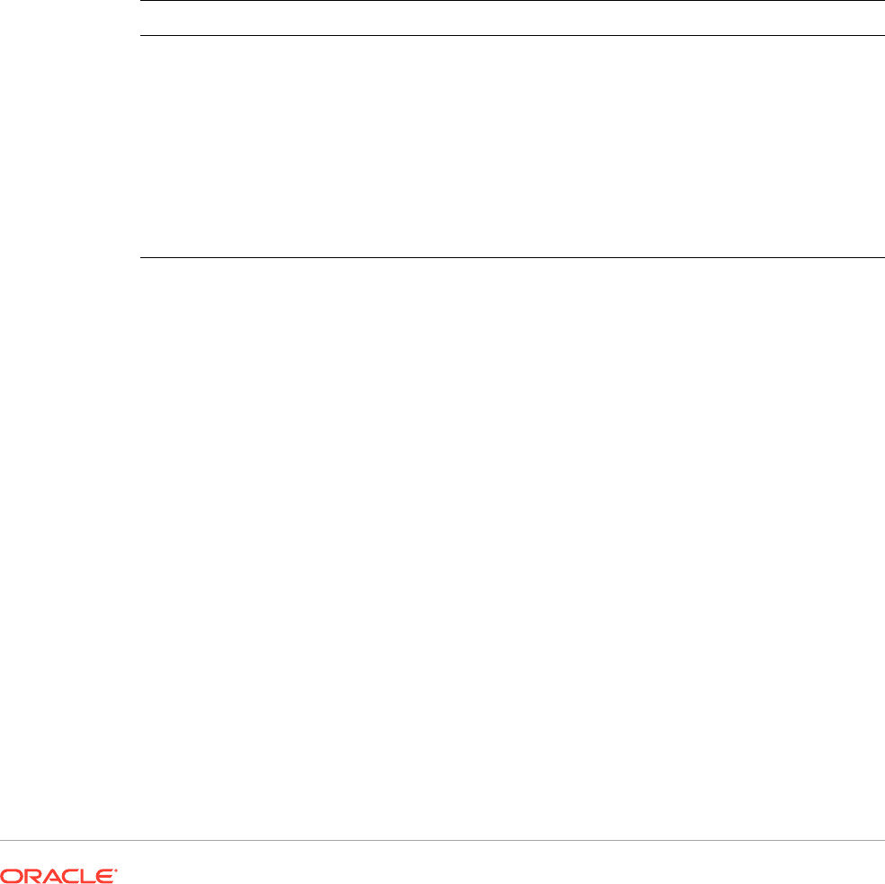
For example, if row 10 has a value of 8, the following expression produces a value of 20 for
that column by calculating 3 * 4 + 8 = 20, following the order of natural precedence:
[10] + 3 * 4
Abs
Abs
is a mathematical function that returns the absolute value of a numeric value, row,
column, or cell. The absolute value of a number is that number without a negative sign. A
negative number becomes positive, while a positive number remains positive.
Syntax:
Abs(argument)
where
argument
is one of the following values:
Argument Description
numeric A numeric value. For example,
Abs(-20)
returns the value 20.
Numeric values can include decimals and negative values. See Numeric
Arguments.
row, column, or cell
reference
A pointer to a row, column, or cell within a grid.
You can specify references in several ways. The reference syntax is:
GridName.GridElement[segment(range)].Property
. See Row,
Column, or Cell Reference Arguments.
function An embedded function.
See Mathematical Functions.
Examples:
Return the value 30:
Abs(-30)
Return the absolute value of the value in row 1:
Abs(row[1])
Calculate the absolute value of the sum of column E:
Abs(column[E].sum)
Point to expanded rows 1 through 3 within design segment 3 of Grid1:
Abs(Grid1.row[3(1:3)])
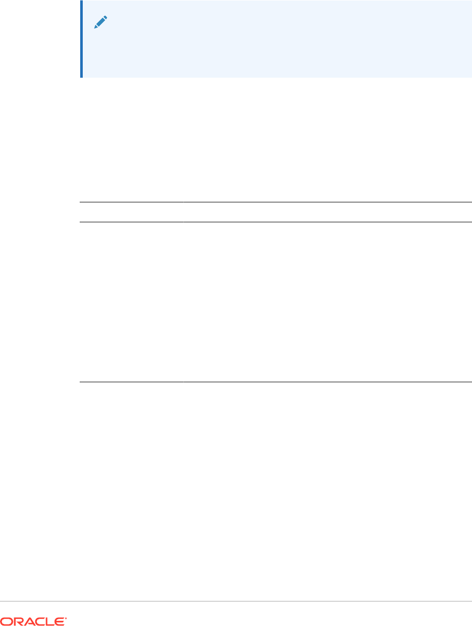
Average
Average
is a mathematical function that returns the average of a group of numeric
values, rows, columns, or cells.
Average
excludes #missing and #error cells when
obtaining the average.
Note:
The calculation does not include missing values regardless of whether they
are suppressed.
Syntax:
Average(arguments)
or
Avg(arguments)
where
arguments
is one or more of the following values:
Argument Description
numeric A numeric value. For example,
Average(10,20,30)
returns the
value 20.
Numeric values can include decimals and negative values. See
Numeric Arguments.
row, column, or cell
reference
A pointer to a row, column, or cell within a grid. For example
Avg(Grid1.row[4(3:5)])
returns the average of grid1, row
segment 4, range 3 through 5.
You can specify references in several ways. The reference syntax is:
GridName.GridElement[segment(range)].Property
. See
Row, Column, or Cell Reference Arguments.
function An embedded function.
See Mathematical Functions.
Examples:
Return the value 20:
Avg(10,30,20)
Return the average of all numbers that are part of three aggregate rows:
Average(row[1],row[6],row[8])
Calculate the average of three aggregate columns; E, G, and I. (The calculation
produces three numbers, then calculates the average of the three numbers.)
Avg(column[E]avg,column[G]avg,column[I.avg)
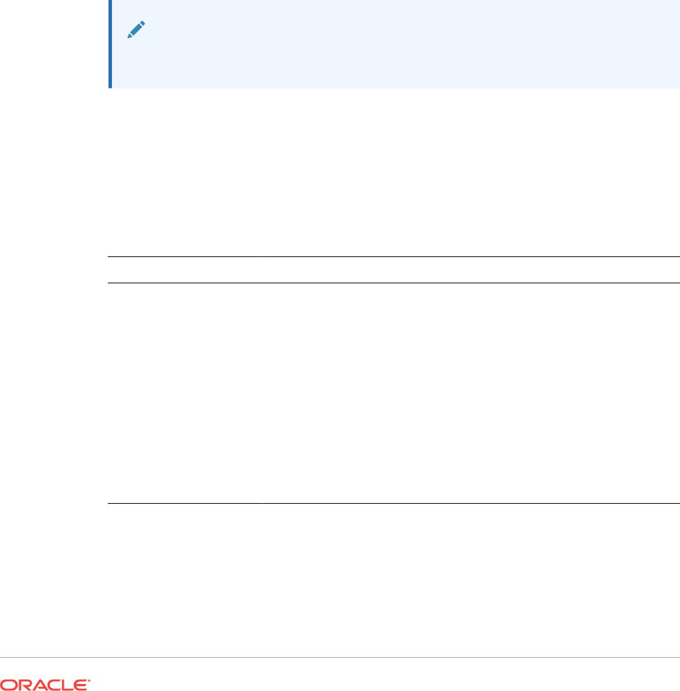
Calculate the average of two columns; E on the current grid and E on grid2. (The calculation
includes all expanded columns.)
Avg(column[E],grid2column[E])
Calculate the average of aggregate row 3 and divide the average by 100:
Avg(row[3])/100
AverageA
AverageA
is a mathematical function that returns the average of a group of numeric values,
rows, columns, or cells.
AverageA
includes #missing and #error cells, which are treated as
zero values when obtaining the average.
Note:
#missing and #error are included only for rows or columns that are not suppressed.
Syntax:
AverageA(arguments)
or
AvgA(arguments)
where
arguments
is one or more of the following values:
Argument Description
numeric A numeric value. For example,
AverageA(10,20,30)
returns the value
20.
Numeric values can include decimals and negative values. See Numeric
Arguments.
row, column, or cell
reference
A pointer to a row, column, or cell within a grid.
You can specify references in several ways. The reference syntax is:
GridName.GridElement[segment(range)].Property
. See Row,
Column, or Cell Reference Arguments.
For example,
AvgA(Grid1.row[4(3:5)]
returns the average of grid1,
row segment 4, range 3 through 5.
function An embedded function.
See Mathematical Functions.
Example:
If a grid has four rows with the values 10, 20, 30, and #error, the following formula in the 5th
row returns the value 15:
AverageA([1:4])

Count
Count
is a mathematical function that returns the number of values in a group of
numeric values, rows, columns, or cells.
Count
excludes
#missing
and
#error
when
obtaining the count.
Syntax:
Count(arguments)
where
arguments
is one or more of the following values:
Argument Description
numeric A numeric value. For example,
Count(10,20,30)
returns the value 3.
Numeric values can include decimals and negative values. See
Numeric Arguments.
row, column, or cell
reference
A pointer to a row, column, or cell within a grid.
You can specify references in several ways. The reference syntax is:
Count(GridName.GridElement[segment(range)].property
.
See Row, Column, or Cell Reference Arguments.
function An embedded function.
See Mathematical Functions.
Examples:
Return the count of three rows: 1, 6, and 8:
Count(row[1], row[6], row[8])
Return the count of 3 columns:
Count( column[E], column[G], column[I])
Calculate the count of two columns located on different grids:
Count( grid1.column[E], grid2.column[E])
Calculate the count of the cell located at row 4, column D:
Count(cell[D,4])
Calculate the count of aggregate row 3 in grid 5:
Count(grid5.row[3])

CountA
CountA
is a mathematical function that returns the number of values in a group of numeric
values, rows, columns, or cells.
CountA
includes #missing and #error cells when obtaining the
count only for rows or columns that are not suppressed.
Syntax:
CountA(arguments)
where
arguments
is one or more of the following values:
Argument Description
numeric A numeric value. For example,
CountA(10,20,30,50)
returns the value 4.
Numeric values can include decimals and negative values. See Numeric
Arguments.
row, column, or cell
reference
A pointer to a row, column, or cell within a grid.
You can specify references in several ways. The reference syntax is:
CountA(GridName.GridElement[segment(range)].property
. See
Row, Column, or Cell Reference Arguments.
function An embedded function.
See Mathematical Functions.
Examples:
If a grid has four rows with the values 10, 20, 30, and #error, the following formula in the 5th
row returns the count of four rows:
CountA([1:4])
Return the count of four rows:
CountA(row[1], row[6], row[8] row[where data yields #error])
Difference
Difference
is a mathematical function that returns the absolute value of the difference of a
numeric value, row, or column subtracted from another numeric value, row, or column.
Syntax:
Difference(arg1,arg2)
where
arg2
is subtracted from
arg1
and is one or more of the following values:
Argument
Description
numeric A numeric value. For example,
Difference(3,5)
returns the absolute
value 2.
Numeric values can include decimals and negative values. See Numeric
Arguments.
Argument Description
row, column, or
reference
A pointer to a row, column, or cell within a grid.
You can specify references in several ways. The reference syntax is:
GridName.GridElement[segment(range)].Property
. See Row,
Column, or Cell Reference Arguments.
The following example returns the difference of two rows on grid1 and grid2:
Difference(grid1.row[1], grid2.row[6])
function An embedded function.
See Mathematical Functions.
Note:
Difference
returns the absolute value of
arg2
subtracted from
arg1
,
whereas the minus sign in subtraction negates a number.
Examples:
Return the absolute value of 8:
Difference(3,-5)
Calculate the difference of two aggregate columns:
Difference(column[E], column[G])
Calculate the difference of two columns that are located on different grids, grid1 and
grid2:
Difference(grid1.column[E], grid2.column[E])
Note:
You can type the text label "Difference" or "Variance".
Eval
Eval
is a mathematical function that evaluates an expression. Use
Eval
as an
embedded function argument to consolidate multiple expressions into one expression.
Syntax:
Eval(
expression)
where
expression
is one or more of the following values:
Argument Description
numeric A numeric value.
Numeric values can include decimals and negative values. See Numeric
Arguments.
row, column, or
reference
A pointer to a row, column, or cell within a grid.
References can be specified in several ways. The reference syntax is:
GridName.GridElement[segment(range)].Property
. See Row, Column,
or Cell Reference Arguments.
function An embedded function.
See Mathematical Functions.
operators Any of the supported arithmetic operators (+, -, *, /, ^, %).
Example:
Divide row 1 by row 2, and then round the data to four places:
Round(Eval([1]/[2]),4)
Note:
In this example, you must use
EVAL
to get the desired result. The following does not
work:
Round(([1]/[2]),4)
.
Max
Max
is a mathematical function that returns the maximum value in a group of numeric values,
rows, columns, or cells.
Syntax:
Max(arguments)
where
arguments
is one or more of the following values:
Argument Description
numeric A numeric value. For example,
Max(10,20,30)
returns the value 30.
Numeric values can include decimals and negative values. See Numeric
Arguments.
row, column, or cell
reference
A pointer to a row, column, or cell within a grid.
You can specify references in several ways. The reference syntax is:
GridName.GridElement[segment(range)].Property
. See Row, Column,
or Cell Reference Arguments.
function An embedded function.
See Mathematical Functions.

Examples:
Return the maximum value in rows 1, 6, and 8:
Max(row[1], row[6], row[8])
Calculate the maximum of the sums of aggregate rows:
Max(row[1].sum, row[2].sum, row[3].sum)
Min
Min
is a mathematical function that returns the minimum value in a group of numeric
values, rows, columns, or cells.
Syntax:
Min(arguments)
where
arguments
is one or more of the following values:
Argument Description
numeric A numeric value. For example,
Min(10,20,30)
returns the value 10.
Numeric values can include decimals and negative values. See
Numeric Arguments.
row, column, or cell
reference
A pointer to a row, column, or cell within a grid.
You can specify references in several ways. The reference syntax is:
GridName.GridElement[segment(range)].Property
. See Row,
Column, or Cell Reference Arguments.
function An embedded function.
See Mathematical Functions.
Examples:
Return the minimum value in rows 1, 6, and 8:
Min (row[1], row[6], row[8])
Calculate the minimum of the sums of aggregate rows:
Min(row[1].sum, row[2].sum, row[3].sum)
PercentofTotal
PercentOfTotal
is a mathematical function that returns the result of a numeric value,
row, column, or cell divided by another numeric value, row, column, or cell which is
multiplied by 100.
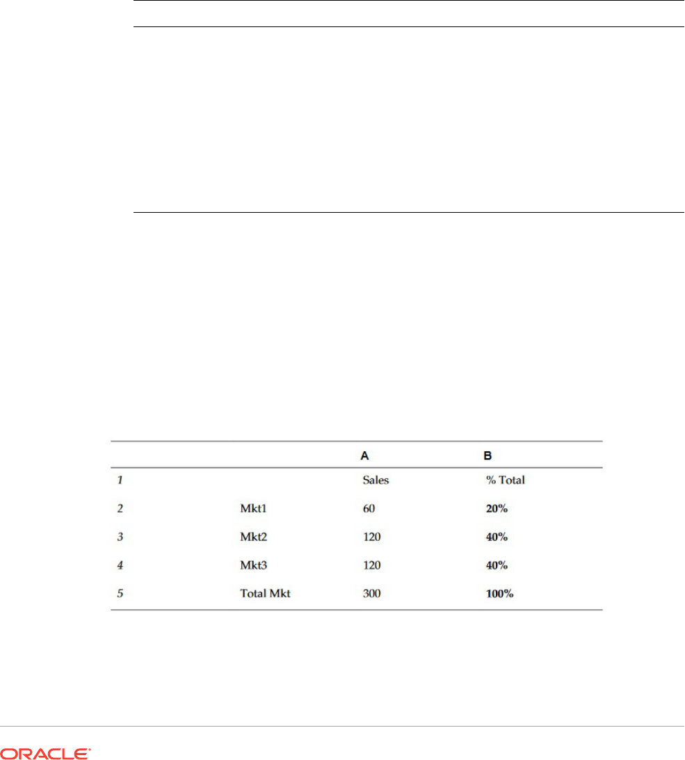
Syntax:
PercentOfTotal (arg1,arg2)
where:
• arg1 is a component of the running total (arg2), usually a row or column reference.
• arg2 is the running total relative to arg1, usually a cell reference containing the grand
total.
• arg1 is divided by arg2 with the result multiplied by 100. Arg1 and arg2 are one or more
of the following values:
Argument Description
numeric A numeric value. For example,
PercentofTotal(100,20)
returns the
value 500.
Numeric values can include decimals and negative values. See Numeric
Arguments.
row, column, or cell
reference
A pointer to a row, column, or cell within a grid.
You can specify references in several ways. The reference syntax is:
GridName.GridElement[segment(range)].Property
. See .Row,
Column, or Cell Reference Arguments
function An embedded function.
See Mathematical Functions.
Examples:
Return the value of 5 percent.
PercentofTotal(20,400)
Divide the value of each cell in column A by the total market value in cell A5, multiply the
result by 100, and display the resulting PercentOfTotal in column B.
PercentOfTotal ([A],[A,5])
Using the above example, the following table shows the
PercentOfTotal
results in column B:
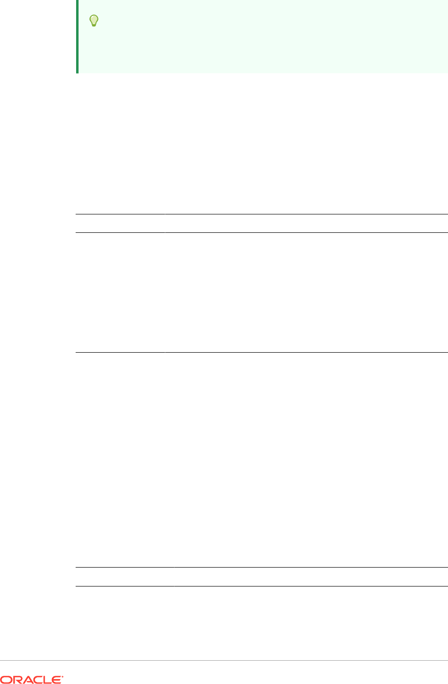
Tip:
You enter the formula by clicking on the header for Column B and using the
formula bar.
Product
Product
is a mathematical function that multiplies all numbers or references and
returns the product.
Syntax:
Product(
arguments
)
where
arguments
is one or more of the following values:
Argument Description
numeric A numeric value. For example,
Product(2,20)
returns the value 40.
Numeric values can include decimals and negative values. See
Numeric Arguments.
row, column, or cell
reference
A pointer to a row, column, or cell within a grid.
You can specify references in several ways. The reference syntax is:
GridName.GridElement[segment(range)].property
. See Row,
Column, or Cell Reference Arguments.
function An embedded function.
See Mathematical Functions.
Example:
Return 40:
Product(2,20)
Round
Round
is a mathematical function that rounds a number up or down by the specified
digits.
Syntax:
Round (arg1,integer)
where
arg1
is one or more of the following values:
Argument
Description
numeric A numeric value. For example,
Round(81.3987,3)
returns the value
81.399.
Numeric values can include decimals and negative values. See
Numeric Arguments.
Argument Description
row, column, or cell
reference
A pointer to a row, column, or cell within a grid.
You can specify references in several ways. The reference syntax is:
GridName.GridElement[segment(range)].property
. See
Row, Column, or Cell Reference Arguments.
function An embedded function.
See Mathematical Functions.
Integer
specifies the number of digits to round the number:
• If
integer
is greater than zero, the number is rounded to the specified number of
decimal places.
• If
integer
is zero, the number is rounded to the nearest integer.
• If
integer
is less than zero, the number is rounded to the left of the decimal point.
Examples:
Round to 3 decimals:
Round(3594.5567,3)=3594.557
Round to the nearest integer:
Round(3594.5567,0)=3595
Round to the thousand, (also known as scaling):
Round(3594.5567,-3)=4000
Sum
Sum
is a mathematical function that returns the summation of a group of numeric values,
rows, columns, or cells.
Syntax:
Sum(arguments)
where
arguments
is one or more of the following values:
Argument Description
numeric A numeric value. For example,
Sum(10,20,30)
returns the value 60.
Numeric values can include decimals and negative values. See Numeric
Arguments.
row, column, or cell
referenc
A pointer to a row, column, or cell within a grid.
You can specify references in several ways. The reference syntax is:
GridName.GridElement[segment(range)].property
. See Row,
Column, or Cell Reference Arguments.

Argument Description
function An embedded function.
See Mathematical Functions.
Examples:
Return the value 30:
sum(10,20)
Return the sum of three rows:
sum(row[1],row[6],row[8])
Calculate the sum of three aggregate columns:
sum(column[E], column[G], column[I])
Calculate the sum of two columns that are located on different grids:
sum(grid1.col[E],grid2.colmn[E])
Truncate/Truc
Truncate
is a mathematical function that removes the specified number of digits from
numeric values.
Syntax:
Trunc(arg1,integer)
where arg1 is one of the following values:
Argument Description
numeric A numeric value. For example, 234.567.
See Numeric Arguments.
row, column, or cell
reference
A pointer to a row, column, or cell within a grid.
You can specify references in several ways. The reference syntax
is:
GridName.GridElement[segment(range)].property
.
See Row, Column, or Cell Reference Arguments.
function An embedded function.
See Mathematical Functions.
Integer
specifies the number of digits to remove:
• A positive
integer
determines the number of digits to the right of the decimal
point.
• A zero (0)
integer
returns the integer located to the left of the decimal point.

• A negative
integer
indicates the number of digits to the left of the decimal point.
Examples:
The following statement uses a positive integer of 2. The first two digits to the right of the
decimal point remain, and the following digit is removed:
Trunc(234.567, 2) = 234.56
The following statement uses a zero (0) integer. All digits to the right of the decimal point are
removed:
Trunc(234.567, 0) = 234
The following statement uses a negative integer of -2. All digits to the right of the decimal
point are removed and the last 2 digits of the integer are truncated.
Trunc(234.567, -2) = 200
Note:
Any formatting previously applied to a cell, column, or row is maintained when you
use the
Trunc
function. The following example shows the results of a
Trunc
function
where the cell value was previously formatted to display three decimal places:
Trunc(234.567, 0) = 234.000
Text Functions
Text functions return report information, such as the report name or the report description.
Related Topics
• About Text Functions
• Annotation
• CellText
• Date
• DataSource
• Footnote
• GetCell
• GetHeading
• GridDimension
• ListofCellDocuments
• MemberAlias
• MemberName
• MemberProperty

• MemberQualifiedName
• Page
• PageCount
• PlanningAnnotations
• ReportAuthor
• ReportCreated
• ReportDesc
• ReportFolder
• ReportModified
• ReportModifiedBy
• ReportName
• ReportRunBy
• RetrieveValue
About Text Functions
Text functions return report information, such as the report name or the report
description. You use text functions in grids or in text objects.
Text Function Considerations
• Enclose text functions in braces:
<<TextFunction (arguments)>>
• You can use spaces between arguments.
• All arguments are enclosed in quotes, except for numeric arguments.
For example, the parameter "NYC, New York" in the function
<<MemberName("Grid1", NYC, New York)>>
should be restated as
<<MemberName("Grid1", "NYC, New York")>>
.
• Arguments related to date formatting are case-sensitive.
• To apply text functions to a grid, create a text row or column, or a heading cell, and
then insert the text function.
Using the Current/Cur Keyword in a Text Function
You can use the
current
keyword with certain text functions to make the formulas
more dynamic, more useful, and less redundant. The
current
keyword can replace
required parameters in text functions. Hard-coded parameters produce the same
results, whereas the
current
keyword can produce dynamic values. For example,
when you use
current
for the Page parameter in a multiple page grid, it produces the
value for each page.
You can use any form of the
current
keyword;
current
, or
cur
.
Current
keywords are
not case-sensitive.

Note:
The
current
keyword is supported in a text object only when using the following
text functions:
MemberName
,
MemberAlias
, and
MemberDescription
, where
current
specifies the Page dimension parameter. However, the Grid name, Row, and
Column must be defined, where applicable, and cannot use the
current
keyword.
Example 1:
In the
GetCell
function, many of the parameters are or may be relative to the current cell in
which the function is entered. Therefore, the
current
keyword can be applied to this function.
The
GetCell
function uses the following syntax:
<<GetCell ("GridName", Row, Column, Page)>>
In the following example, the hard-coded parameters for
GetCell
return the same cell value
of Grid 1, cell 1A, page 1 across multiple pages:
<<GetCell ("Grid1", 1, A, 1)>>
The next example uses the
current
keyword with the
GetCell
function. The cell where the
function is entered displays different values for each page. Notice that the
current
keyword is
also applied to the grid name. If the grid name is changed, the text formula is still correct.
<<GetCell ("current", 1, current, current)>>
Example 2
When you use the
current
keyword in a cell that expands, the results are relative to the
expanded cell.
The following example uses
GetCell
functions in an expanded cell (Column A expands to
columns Qtr1, Qtr2, Qtr3 and row 1 expands to rows East and West). Text Row 1 uses the
current
keyword for the Column parameter; Text Row 2 uses a hard-coded value for the
Column parameter.
Name Description
. Qtr1, Qtr2, Qtr3
East, West #
Text Row 1
<<GetCell(cur, 1, cur, cur)>>
Text Row 2
<<GetCell(current, 1, A, 1)>>
The results are displayed in the following table.
Name
Quarter 1 Quarter 2 Quarter 3
East
5,120 4,502 7,304
West
3,405 2,300 4,462
Name Quarter 1 Quarter 2 Quarter 3
Text Row 1
5,120 4,502 7,304
Text Row 2
5,120 5,120 5,120
• Text Row 1 uses the
current
keyword for the Column parameter, which results in
the update of the current column of each expanded cell (Qtr1, Qtr2, Qtr3). Also,
because the
current
keyword is used for the Page parameter, the values in Text
Row 1 update each page relative to the current page of the grid.
• Text Row 2 uses a hard-coded value for the Column parameter (A), which results
in the same value of 5,120 for all quarters. A hard coded reference to a Column
parameter returns the same top left value of the column and row.
Table 11 Text Functions that Support the Current Keyword
Text Function Example
<<DataSource("GridName.Axis[ID]",I
nfoType)>>
Parameters where applicable:
•
GridName
: supported in all cells
•
InfoType
: not applicable
<<DataSource(current, "App")>>
Note:
The current grid
name is used.
Table 11 (Cont.) Text Functions that Support the Current Keyword
Text Function Example
<<GetCell("GridName",Row,Col,Page
)>>
Parameters where applicable:
•
GridName
: supported in all cells
•
Row
: supported in all cells
•
Col
: supported in all cells
•
Page
: supported in all cells
<<GetCell(cur, 1, cur, current)>>
<<GetCell(cur, 1(3), cur,
current)>>
Note:
The value from
the third
(expanded) row
of row 1 is
shown.
<<GetCell(cur, cur, A, current)>>
<<GetCell(cur, cur, A(B),
current)>>
Note:
The value from
the second
(expanded)
column of
column A would
be shown.
Table 11 (Cont.) Text Functions that Support the Current Keyword
Text Function Example
Use the following in a data row or column
heading:
<<MemberName("DimName")>>
Use the following in a non-data row or column
heading:
<<MemberName("GridName",Row/Col/
Page,"DimName")>>
Use the following parameter where applicable:
DimName
: Heading cells only
<<MemberName(current)>>
<<MemberName("current", Row/Col/
Page, "current")>>
Note:
Returns the
name of the
member of the
data row,
column, or page
that corresponds
to the dimension
where the
heading cell is
located. This can
be used with the
<<MemberDimen
sion>>
function
to create custom
headings for a
grid.
<<CalcStatus("GridName",Row,Col,Pa
ge)>>
Note:
The parameters
allowing the
current
keyword are
highlighted in
bold.
<<CellText("GridName", Row,
Column, Page)>>
<<CellText("GridName", Row,
Column, Page, MemberOverride)>>
Table 11 (Cont.) Text Functions that Support the Current Keyword
Text Function Example
<<GridDimension("GridName","Axis",
index)>>
Note:
The parameters
allowing the
current
keyword are
highlighted in
bold.
<<MemberAlias("DimName")>>
<<MemberAlias("GridName",
"DimName")>>

Table 11 (Cont.) Text Functions that Support the Current Keyword
Text Function Example
<<MemberAlias("GridName", Row|Col|
Page, "DimName")>>
<<MemberDesc("DimName")>>
<<MemberDesc("GridName",
"DimName")>>
<<MemberDesc("GridName", Row|Col|
Page, "DimName")>>
<<MemberName("DimName")>>
<<MemberName("GridName",
"DimName")>>
<<MemberName("GridName", Row|Col|
Page, "DimName")>>
<<MemberQualifiedName("DimName")>>
<<MemberQualifiedName("GridName",
"DimName")>>
<<MemberQualifiedName("GridName",
Row|Col|Page, "DimName")>>
<<MemberProperty(DimensionName,
Property)>>
<<MemberProperty("GridName",
DimensionName, Property)>>
<<MemberProperty("GridName", Row|
Col|Page, DimensionName,
Property)>>
Table 11 (Cont.) Text Functions that Support the Current Keyword
Text Function Example
<<ProcessManagementStatus("GridNam
e",Row,Column,Page)>>
Note:
The parameters
allowing the
current
keyword are
highlighted in
bold.
<<ListOfCellDocuments("GridName",F
ileName)>>
Note:
The parameters
allowing the
current
keyword are
highlighted in
bold.
<<GridDimension("GridName","Axis",
Index)>>
Parameters, where applicable:
•
GridName
: supported in all cells
•
Axis
: Heading cells only
•
Index
: Heading cells only
<<GridDimension(cur,"Page",1)>>
<<GridDimension(cur,cur,cur)>>
Note:
The dimension
name
corresponding to
the heading cell
is shown.
Table 11 (Cont.) Text Functions that Support the Current Keyword
Text Function Example
<<GetHeading("GridName",Page,Ref,O
ffset)>>
<<GetHeading("GridName",Page,Ref,"
Delim")>>
Parameters where applicable:
•
GridName
: supported in all cells
•
Page
: supported in all cells
•
Ref
: supported for in all cells, but should
not be used in heading cells*
•
Offset
: Heading cells only
•
Delim
: not applicable
<<GetHeading(cur, cur, A, " - ")>>
<<GetHeading(cur, cur, 1, " - ")>>
Note:
In the above
examples, all
headings in
column A and
row 1 are shown
for the current
page.
<<GetHeading(cur, cur, A, cur)>>
Note:
The heading in
column A is
shown for the
dimension that
corresponds to
where the
heading cell with
the formula is
located.
<<GetHeading(cur, cur, cur, " -
")>>
Note:
If used within a
row text cell, the
result is all of the
headings in the
current column
separated by a "
- ". This allows
users to repeat
Table 11 (Cont.) Text Functions that Support the Current Keyword
Text Function Example
column headings
after a manual
page break.
*Use of the
current
keyword for the parameter "reference " is limited. The
current
keyword
cannot be used in the
GetHeading
function when it is entered as a "custom heading" in a row
or column because circular reference is created. You can use the
current
keyword as the
third parameter within a cell that is part of a text row or column which is not in the heading area
of the grid. For example, if you add the following formula in cell A3 where row 3 is a text row:
<<GetHeading(cur,cur,cur,1)>>
, the result is the first heading of column A. You can use
the GetHeading function within a heading cell. However, the
reference
parameter should not
use the
current
keyword. For example, when you enter in the heading cell of column B
<<GetHeading(cur, cur, A, cur)>>
, the column A heading is returned.
Annotation
Annotation
returns the requested information about an annotation within a grid object. You
can define what information to return.
Syntax:
<<
Annotation
("GridName", Row, Col, Page, Attributes, Reference, Attachments)>>
<<Annotation
("GridName", Row, Col, Page)>>
<<
Annotation
("GridName", Row, Col, Page, Attributes, Reference)>>
<<
Annotation
("GridName", Row, Col, Page, Attributes, Attachments)>>
<
Annotation
("GridName", AllRows, AllCols, Page, Attributes, Attachments)>>
where:
• GridName is the name of the grid containing the annotations. The "current" keyword is
supported when Attribute is used in a grid's text cell or custom heading.
• Row is the row number on the grid. The "current" keyword is supported in when Attribute
is used in a grid's text cell or custom heading.
Note:
To select all rows,
row
can be replaced with the keyword
AllRows
.
• Col is the column reference (letter) on the grid. The "current" keyword is supported when
Attribute is used in a grid's text cell or custom heading.

Note:
To select all Columns,
Col
can be replaced with the keyword
AllCols
.
• Page is a numeric value representing the index of member combinations on all
page dimensions of the grid. The first page dimension combination in a grid has an
index of 1, the second page dimension combination has an index of 2, and so on.
• Attributes identify the information to be returned from the annotation. They may
include the keyword All (default value) or a combination of one or more of the
following keywords:
Title & Description & Author & Date & Category
.
Attribute keywords can be arranged in any order of output. Each attribute must be
separated with an ampersand (&).
• Reference is a keyword noting which annotations will be returned, where:.
–
All
(default) returns the initial annotation and all replies.
–
Top <n>
returns the initial annotation and first <n> replies.
–
Bottom <n>
returns the initial annotation and the last <n> replies. The initial
annotation is always shown and the number <n> does not include the initial
annotation.
–
BottomOnly <n>
returns the last <n> replies. The initial annotation shown for 4
or less <n> replies; the initial annotation with 5 or more <n> replies is not
shown.
–
First
returns the initial annotation only.
–
Replies
returns all replies. The initial annotation is not shown.
• Attachments is a boolean (
true/false
) value indicating whether attachments
associated with the annotation should print with the report where:
–
True
means that attachments will print at the end of the report.
–
False
means that no attachments will print.
Examples:
<<Annotation("Grid1", cur, A, cur, All, All, true)>>
<<Annotation("Grid1", cur, A, cur, Title & Description & Author & Date &
Category, Top 10, true)>>
<<Annotation("Grid10", 284, AB, cur, Title & Description & Date &
Category, Bottom 10, false)>>
<<Annotation("Grid1", cur, A, cur, Title & Description & Author,
BottomOnly 4, false)>>
<<Annotation("Grid Name", 1, A, 1, All)>>
<<Annotation("Grid Name","AllRows", "AllCols", 1, All)>>
<<Annotation("Grid Name", 1, A, 1, All, First)>>
<<Annotation("Grid Name", 1, cur, cur, All, Replies)>>
<<Annotation("Grid Name", 1, cur, cur)>>

<<Annotation("Grid Name",1, cur, cur, Desc, Replies)>>
<<Annotation(cur, cur, A, cur, Desc)>>
<<Annotation(cur, 3, ABC, cur, title & Desc, true)>>
<<Annotation("folder1\folder2\Grid2", 3,A,cur, Title & Description, true)>>
<<Annotation(current, 294, AB, cur, Title & Description, Top 19)>>
<<Annotation(current, 39, AB, cur, Title & Description & Author, Bottom 40)>>
Behavior of Annotations in Text Boxes
The behavior of annotations in grid text rows and text boxes when using the "cur" keyword is
different.
• For text rows, you can use the "cur" keyword.
For example,
<<Annotation("Grid1", 1, A, cur, All, All, true)>>
• For text boxes, the "cur" keyword does not return anything. As a result, you would enter
<<Annotation("Grid1", 1, A, 1, All, All, true)>>
CellText
CellText
is a text function that retrieves the textual content from the following database
connections:
The row, column, and page arguments apply to the intersection in a grid that contains the
linked text or note.
Syntax:
<<CellText("GridName", Row, Column, Page)>>
CellText
can also provide an override of the grid’s "natural" point of view (POV) to a member
selection when a cell does not exist in a grid.
Syntax:
<<CellText
("GridName", Row, Column, Page, MembeOverride)>>
See CellText Using MemberOverride for details.
Argument Description
GridName Name of a grid. This value must be enclosed in quotation marks
Row Numeric value representing the row number of the grid. The first row in a grid has
an index of 1, the second row has an index of 2, and so on.
Column Letter that represents the column of the grid. The first column in a grid has an index
of A, the second column has an index of B, and so on.
Page Numeric value representing the page dimension index of the grid. The first page
dimension in a grid has an index of 1, the second page dimension has an index of
2, and so on.
MemberOverride String of dimensions and corresponding member selections that override the
CellText
POV. See CellText Using MemberOverride.
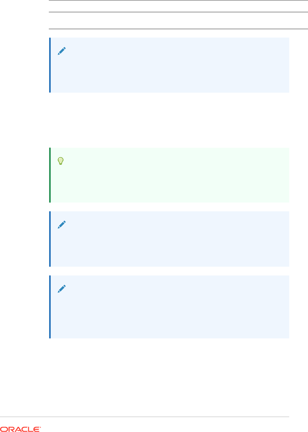
Argument Description
AllRows/AllCols Keywords that allow for an all row or column reference. See CellText Using AllRows/
AllCols.
Note:
If the row or column parameters refer to a segment that expands, the top-left
expanded cell is used. You can refer to any expanded cell using the "range"
notation.
Example:
Create a report with linked text in the cell that is in row 21, column B of a grid and that
is on the first page dimension.
<<CellText("mygrid",21,B,1)>>
Tip:
To view result-time rows and columns, select View, then Row & Column
Headers in Web Preview, and then preview the report by clicking Web
Preview.
Note:
CellText
only supports the
Current
keyword when used in a grid cell; not in
a text box object, header, or footer. See Using the Current/Cur Keyword in a
Text Function.
Note:
If no textual commentary exists for a cell intersection that the
CellText
function references, a URL for the first cell file attachment in the cell is
displayed. To list the cell file attachments, use the ListofCellDocuments text
function.
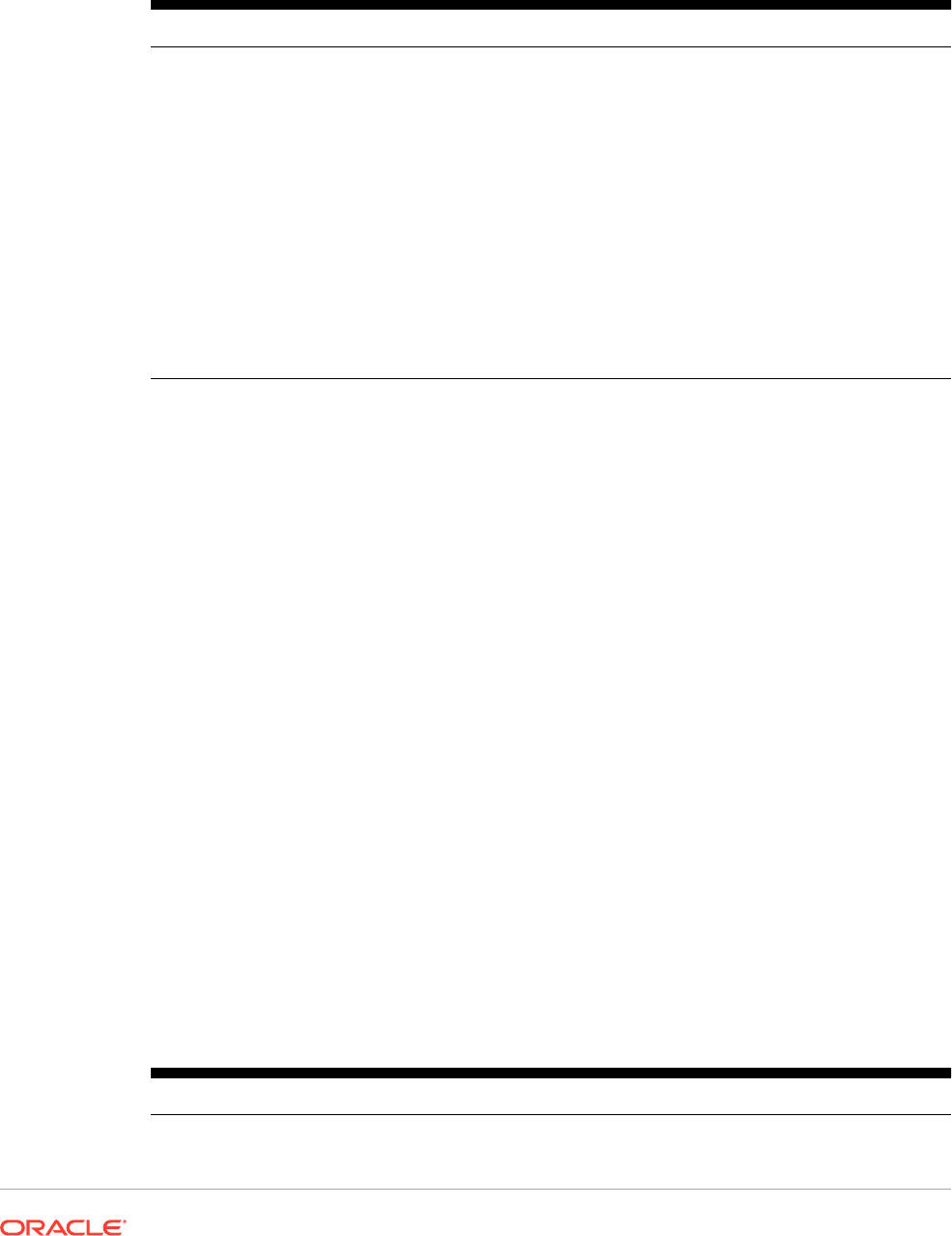
CellText Using AllRows/AllCols
Table 12 CellText Examples Using AllRows/AllCols
Example Description
<<CellText("Grid1",3,AllCols,1)>>
Includes cell text that occurs on any column of row
3, page 1.
<<CellText("Grid1",Curr,Allcols,1)>>
Includes cell text that occurs on any column of the
current row ("Curr"), page 1.
<<CellText("Grid1",Curr,Allcols,Curr)>>
Includes cell text that occurs on any column of the
current row ("Curr"), current page.
<<CellText("Grid1",AllRows,C,1)>>
Includes cell text that occurs on any row of column
C, page 1.
<<CellText("Grid1",AllRows,Allcols,2)>>
Includes cell text that occurs on any cell on page
2. "Any cell" meaning any row/column since
AllRows/AllCols is specified for both row and
column.
<<CellText("Grid1", AllRows, Allcols,
Curr)>>
Includes cell text that occurs on any cell on the
current page.
CellText Using MemberOverride
MemberOverride can consist of one or more dimensions. It uses the following format:
DimensionName = MemberName, DimensionName = MemberName
where:
DimensionName is the name of an override dimension.
MemberName is the name of the override member for the dimension.
Follow these guidelines when you specify member overrides:
• If you specify two or more member overrides, separate them with a comma (,) or a
semicolon (;) and enclose each dimension and member name in quotation marks (" "),
For example:
"Entity"="Acme","Period"="Q1"
• If you specify only one member override, do not include the separator character.
• Enclose dimension names and member names in quotation marks (" ") if they contain any
of the following characters: ; , = ( ) < >.
• For a single member override, the parameter may be enclosed in quotation marks (" ").
For example,
CellText
is properly evaluated if you use the following member override
statement:
"Scenario=Budget"
Table 13 CellText Examples Using MemberOverride
Example Description
<<CellText(cur, cur, A, cur)>>
Existing syntax with no dimension override
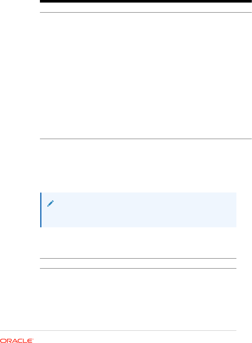
Table 13 (Cont.) CellText Examples Using MemberOverride
Example Description
<<CellText(cur, cur, A, cur,
Scenario=Budget)>>
New syntax with one dimension override
<<CellText("Grid Name", 1, A, current,
Value = "Entity Currency")>>
One dimension override using quotation marks in
the member name
<<CellText("Grid Name", 1, A, cur,
Value = Entity Currency)>>
No quotation marks in the member name that
contains a space
<<CellText("Grid Name", 1, A, cur,
"Value=$USD" = Entity Currency)>>
Quotation marks surrounding dimension name
that contains an equal sign
<<CellText(Grid1, 1, cur, cur, Value =
Entity Currency, Scenario=Actual)>>
Two-dimension override that uses a comma
separator
<<CellText(Grid1, 1, cur, cur, Value =
Entity Currency; Scenario=Actual)>>
Two-dimension override that uses a semicolon
separator
<<CellText("Current", 34, BB, cur,
"Value"= Entity Currency,
Scenario=Actual; Period = Qtr3)>>
Three-dimension override that uses comma and
semicolon separators
<<CellText(cur, 1(3), A(B), cur, 300 =
ABC , "Americas, Value=(in $USD);" =
"Entity Currency (USD)" ,
Scenario=Actual)>>
Four-dimension override
Date
Date
is a text function that returns the date and time that an online report is populated
with data, or the date and time that a snapshot report is saved. The date and time is
retrieved from the report server and corresponds to the country in which the report
server is located. You can use
Date
in a text box, text cell, or a row or column heading.
Note:
The date and time format vary by locale. The examples in this topic are
examples for the US.
Syntax:
<<Date("format,TimeZoneId")>>
Argument Description
format Defaults to the user preference for date/time. Valid values are those accepted
by Java
SimpleDateFormat
, or "user" or empty ("user").
Date and time format characters are case-sensitive.

Argument Description
TimeZoneId Valid values are those accepted by Java
TimeZone.getTimeZone()
, or the
server time zone. For example, for
TimeZone.getTimeZone()
to specify the
east coast, enter: "America/New_York".
When using TimeZoneID, enclose the
format
parameter within quotation
marks. This applies only when TimeZoneId is indicated. You do not need to
update reports prior to the TimeZoneId enhancement.
Table 14 Date and Time Format Characters
Format Characters Meaning Data Type Example
G era designator text AD
M month in year text or number If the month is July: M
displays: 7 MM displays: 07
MMM displays: Jul MMMM
displays: July
d day in month number 10
h hour in am/pm (1-12) number 11
H hour in day (0-23) number 22
m minute in hour number 30
s second in minute number 25
S millisecond number 978
E day in week text E: Tue EE: Tuesday
D day in year number 189
F day of week in month number <<Date("dd-MMM-yy ‘is
the’ F 'th ' E 'of' ‘MMM")>>
displays:
24-Dec-02 is the 4th Tue of
Dec
w week in year number 27
W week in month number 2
a am/pm marker text PM
k hour in day (1-24) number 23
K hour in am/pm (0-11) number If the time is 3:37PM: 3
z time zone text Pacific Standard Time
y year number 2002,02
' literal text text <<Date(" D’the day
of ’yyyy")>> displays:105th
day of 2002

Table 14 (Cont.) Date and Time Format Characters
Format Characters Meaning Data Type Example
' ' two single quotes to
produce one single quote
text <<Date("k:mm ‘O’’Clock’
a")>> displays: 6:15
O’Clock PM
N
o
t
e
:
U
s
e
2
s
i
n
g
l
e
q
u
o
t
a
t
i
o
n
m
a
r
k
s
t
o
p
r
o
d
u
c
e
a
s
i
n
g
l

Table 14 (Cont.) Date and Time Format Characters
Format Characters Meaning Data Type Example
e
q
u
o
t
e
o
r
a
n
a
p
o
s
t
r
o
p
h
e
a
s
i
n
O
’C
l
o
c
k
(
O
’
’C
l
o
c
k
)
.
Considerations when using format characters:
• The number or count of format characters determines the format:
– For text, less than four pattern letters means use a short or abbreviated form, if it
exists.
– Four or more pattern letters means use full form.
– M or MM means use the month as a number.
– MMM means use the three-letter abbreviation for the month.
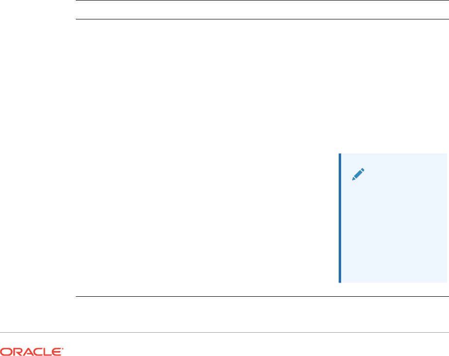
– MMMM means use the full name of the month.
For example, if the date is April 24:
<<Date("dd-M-yy")>> displays 24-4-02
<<Date("dd-MM-yy)>> displays 24-04-02
<<Date("dd-MMM-yy")>> displays 24-Apr-02
<<Date("dd-MMMM-yy")>> displays 24-April-02
• For numbers, the number of pattern letters is the minimum number of digits.
Shorter numbers are padded with zeros. Year is a special case. If you use "yy", the
last two digits of the year are displayed, but if you use "yyyy," the four-digit year is
displayed.
For example, if the month is February:
<<Date("MM-yyyy")>> displays 02-2002
• All upper and lower case alphabet characters are considered patterns, regardless
of whether they are designated format characters.
• Enclose literal text within single quotation marks. To use a single quotation mark in
literal text, enclose the text within single quotes and use two single quotes for the
apostrophe.
For example, the format to print 4 o’clock is:
<<Date("hh 'o''clock' ")>>
Examples:
Date Format Result
<<Date("d/M/yy")>>
23/3/02
<<Date("d-MMM-yy")>>
23-Mar-02
<<Date("EEEE, MMMM dd, yyyy")>>
Tuesday, March 23, 2002
<<Date("h:mm:ss a")>>
12:52:05 PM
<<Date("h:mm:ss a zzzz")>>
12:52:05 PM Eastern Standard Time
<<Date("EEEE, MMMM dd, yyyy G
'time:' h:mm:ss a zzzz")>>
Tuesday, March 23, 2002 AD time: 12:52:05
PM Eastern Standard Time
<<Date("hh 'o’’clock' a, zzzz")>>
12:00 PM, Eastern Standard Time
Note:
You must use
two single
quotation marks
to produce one
single quotation
mark in the text
of your formatted
result.
DataSource
DataSource
is a text function that returns the application name, database, or alias table name
of a grid. Use
DataSource
in a text box, text cell, or a row or column heading.
Syntax:
<<DataSource("GridName.Axis[ID],Info Type")>>
Argument Description
GridName (Required) Any grid in a report, enclosed in quotes.
Axis[] (Optional) A pointer to a design segment of the grid. Axis can be one of the following
keywords:
row
,
col
, or
column
, and it is not case-sensitive.
For example,
<<DataSource("Grid1.Row[1]",DB)>>
When
Axis
is not provided, the grid's default information is returned. Use
Axis
when a grid has multiple database connections.
ID (Required if
Axis
is used) Indicates the design-time, row number, or column letter
from which the database connection information is retrieved. If ID points to an invalid
or nonexistent row or column ID, the grid default settings are used. In addition, if a
grid does not have a secondary database connection, the grid default settings are
used.
For example,
<<DataSource("Grid1.Col[A]",DB)>>
InfoType (Required) One of the following keywords:
• App returns the application name.
• DB returns the database name.
• Alias returns the alias table name. To return the alias, the grid must have the
alias table enabled. By default, the alias table is disabled.
• Name returns the database connection name associated with the specified grid.
Note:
"Server" is not supported as an argument for InfoType.
for Planning data sources.
Note:
All arguments are case insensitive.
Example 1:
Insert data source information in your report:
<<DataSource("Grid1", App)>>

Example 2:
Show the database name of the data source associated with the heading where the
function was entered:
<<DataSource(cur, DB)>>
Note:
DataSource
supports the
current
keyword. See Using the Current/Cur
Keyword in a Text Function.
Footnote
The
Footnote
text function, used in Text Objects only, returns the requested
information about footnotes within a given report object.
Footnote
prints information
about footnotes that occur in the object specified, or in all the objects in the report if
the first parameter is set to "all". When a grid is referenced, all the footnotes on the
grid are printed. The partial POV footnotes print first, followed by any full POV
footnotes. The full POV footnotes print in order based on the location of the cell from
top left to bottom right, page by page. More than one syntax is supported.
Syntax:
Footnote("ObjectName, Attributes, Reference, Attachments")
Footnote("ObjectName")
Footnote("ObjectName", Attributes)
Footnote("ObjectName", Attributes, Reference)
Footnote("ObjectName", Attributes, Attachments)
Argument Description
ObjectName Name of the report object containing the footnotes. If "all", the function
returns all available footnotes from all objects in the report. The
ObjectName parameter is updated when a grid object is renamed.
Attributes Information returned from the footnote. This may include the following
keywords:
•
All
(default value)
• A combination of one or more of these keywords;
Title
,
Description (Desc)
,
Author
,
Date
,
Category
The Attributes keywords may be arranged in the preferred order of output.
Separate each attribute with an ampersand (&).

Argument Description
Reference Keyword denoting which annotations will be returned where:
•
All
(default value)—The initial annotation and all replies.
•
Top <n>
—The initial annotation and first replies. (The initial annotation
is always shown, and the number does not include the initial
annotation.)
•
Bottom
—The initial annotation and the last number of replies specified
in Bottom <n>. (The initial annotation is always shown, and the
number does not include the initial annotation.)
•
BottomOnly <n>
—The last replies. The initial annotation is not shown
unless there are less replies than the
BottomOnly <n>
number. For
example,
BottomOnly 5
for an annotation with five replies does not
show the initial annotation, but for an annotation with four replies, the
initial annotation is shown.
•
First
—The initial annotation only.
•
Replies—
All the replies except the initial annotation.
Attachments Boolean (true/false) value indicating whether any attachments should be
printed with the footnote.
•
True
—Attachments print along with the report, at the end.
•
False
(default value)—Attachments do not print.
Examples:
<<Footnote("Grid1", All, All, true)>>
<<Footnote(All, All, All, true)>>
<<Footnote(All, All, Bottom 2, true)>>
<<Footnote(All, All, BottomOnly 20, true)>>
<<Footnote(All, All, First, true)>>
<<Footnote(All, All, Replies, true)>>
<<Footnote("Grid1", Title & Description & Author & Date & Category, All, true)>>
<<Footnote("Text1", Title & Description & Date & Category, Top 10, false)>>
<<Footnote("Image1", Title & Description & Author, Bottom 4, false)>>
<<Footnote("Text1", Title&Description&Author, BottomOnly 12)>>
<<Footnote("Image1", Title&Description&Author, First)>>
<<Footnote("Grid2", Title&Description&Author, Replies)>>
<<Footnote("Grid Name")>>
<<Footnote(all, All)>>
<<Footnote(cur, Description)>>
<<Footnote(cur, title & Description, true)>>
<<Footnote(cur, title & Author & Description, false)>>
<<Footnote("folder1\folder 2\Grid1", title & Description&Category, Top20)>>

<<Footnote("folder1\folder 2\Grid1", title & Description&Category, Bottom
2)>>
<<Footnote("folder1\folder 2\Chart2", title & Description, Top 20,
False)>>
<<Footnote("current", title & Description, All)>>
<<Footnote("current", title & Description, first)>>
<<Footnote(All, Title&Description&author, Top 40, true)>>
GetCell
GetCell
is a text function that returns a data value from a grid.
Syntax:
<<GetCell("GridName", Row, Column, Page)>>
Argument Description
GridName Name of a grid or the
Current
keyword.
Row Numeric value representing the row number of the grid. The first row in a grid has
an index of one, the second row has an index of two, and so on. The
Current
keyword can also be used.
Column Letter representing the column of the grid. The first column in a grid has an index
of A, the second column has an index of B, and so on.
Page Numeric value representing the page dimension index of the grid. The first page
dimension in a grid has an index of one, the second page dimension has an index
of two, and so on.
Considerations when using
GetCell
:
• If the row or column parameters refer to a segment that expands, the top-left
expanded cell is used. You can refer to any expanded cell using the "range"
notation.
•
GetCell
only supports the
Current
keyword when used in a grid cell; not in a text
box object, header, or footer.The
Current
keyword can be used in any of the
parameters to make the function more dynamic. See Using the Current/Cur
Keyword in a Text Function.
Example:
Set up a grid to show the net income for several quarters, and display this value in a
text box that contains an executive summary of the report.
The grand total for the period was <<GetCell("mygrid",21,B,1)>>
The report is created with the value in the cell that is in row 21, column B of a grid, and
is on the first page dimension.
GetHeading
GetHeading
is a text function that obtains text headings from a specified grid.
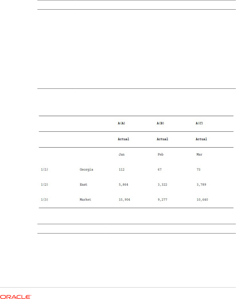
Syntax:
<<GetHeading("GridName",
Page, Reference, Offset)>>
<
<GetHeading("GridName",
Page, Reference, "
Delimiter")>>
Argument Description
GridName Name of a grid containing the heading to extract. The
Current
keyword can also
be used.
Reference View time reference of the heading to obtain. The
Current
keyword can also be
used. See Row, Column, or Cell Reference Arguments.
Offset Number that represents the dimension in a row or column heading with more than
one dimension.
A numeric offset returns a single dimension heading. For example, in a row
heading with three dimensions, you can specify (starting from left to right) "1" to
return the first dimension, "2" to return the second dimension, and "3" to return the
third dimension.
"Delimiter" Quoted string that separates all headings from the row or column. If you provide a
delimiter, you obtain all headings in the reference, separated by the provided
delimiter.
Examples:
Use
GetHeading
to return the following column and row headings.
Use the syntax below to return the data in the previous sample grid:
GetHeading Example
Gets or Returns
GetHeading("Grid1",1,A,2)
Jan
GetHeading("Grid1",1,A(B),
2)
Feb
GetHeading("Grid1",1,A(C),
-)
Actual - Mar
GetHeading("Grid1",1,1,1)
Georgia
GetHeading Example Gets or Returns
GetHeading("Grid1",1,1(2),
1)
East
GetHeading("Grid1",1,1(2),
2
<error> (it is an invalid reference)
GetHeading("Grid1",1,1(3),
-)
Market
Note:
GetHeading
only supports the
Current
keyword when used in a grid cell; not
in a text box object, header, or footer. See Using the Current/Cur Keyword in
a Text Function.
GridDimension
GridDimension
is a text function that returns the name of a dimension on a grid's
page, column, or row axis.
Syntax:
<<GridDimension("GridName", "Axis", index)>>
Argument Description
GridName Name of a grid in the report enclosed in quotation marks. The
Current
keyword can also be used.
Axis Grid axis where the dimension is placed: page, row, or column. Keywords must
be used. The
Current
keyword can also be used.
index Numeric value representing the offset or index of the dimension on the named
axis. The first dimension on an axis has an index of one, the second dimension
has an index of two, and so on.
You can use the
Current
keyword on a heading cell only (page, row, or
column).
Example:
A shared grid, named mygrid, has several dimensions on each row, column, and page
axes, and displays the name of the first dimension on the row axis in a text box.
Because the dimension may change in the future, you use the
GridDimension
function
in the text box. Type the following in the text box:
This report is based on the <<GridDimension("mygrid","Row",1)>>
dimension.
Note:
See Using the Current/Cur Keyword in a Text Function.
ListofCellDocuments
ListofCellDocuments
is a text function that returns a list of all cell documents and their file
attributes selected to be retrieved from cells within a report. You can use this function in a text
box, text cell, or text cell heading.
Note:
ListofCellDocuments
supports the Current keyword. See Using the Current/Cur
Keyword in a Text Function.
Syntax:
ListofCellDocuments("GridName",FileName,Description)
Argument Description
GridName
Name of a grid in the report.
FileName Name of the cell document.
Description Description of each cell document.
Example:
Two grids in a report are selected to print cell document information. In Grid1, the file name
and description of the extracted cell documents are requested. In Grid2 only the file name is
requested.
<<ListOfCellDocuments ("Grid1",FileName,Description>>
<<ListOfCellDocuments ("Grid2",FileName)>>
The resulting list might look similar to the following, where Grid1 has two attached
documents, and Grid2 has one attached document:
Attached Documents:
April Variance High Volume
April Variance Low Volume
May Variance
MemberAlias
Note:
This function is available only with Oracle Essbase or Planning as the
database connection.
MemberAlias
is a text function. Based on the syntax used, it returns the alias of the
member assigned to a dimension in the row, column, page, or Point of View (POV).
• The following syntax returns the alias of a row heading, column heading, or page.
The syntax can be deployed from any heading cell, text cell, or text box object and
can reference any grid in a current report.
<<MemberAlias("GridName", Row/Col/Page, "DimName")>>
• The following syntax returns the alias in a row heading, column heading, or page.
The syntax can be deployed from any row, column, or page heading in a grid that
is designated as a custom heading. To designate a custom heading, click the
page, row heading, or column heading, and then select Custom Heading on the
property sheet. You can add the function in the space provided below the custom
heading.
<<MemberAlias(
"DimName")>>
• The following syntax returns the alias of a grid or user POV. The syntax can be
deployed from any text cell or text box object and can reference any grid and
corresponding POV in a current report.
<<MemberAlias("
GridName, "POV DimName")>>
Argument Description
GridName Name of the grid
Row/Col/Page Numeric value representing the index of member combinations on all page
dimensions of the grid. The first page dimension combination in a grid has
an index of 1, the second page dimension combination has an index of 2,
and so on.
DimName Name of a dimension in the grid row, column, or page.
POV DimName Name of the dimension on the grid or user POV.
Examples:
Yield the alias Diet Root Beer, which is the alias that is assigned to the Product
dimension in Grid1, column A:
<<MemberAlias("Grid1", A, "Product")>>
<<MemberAlias(current, A, "Product")>>
Yield the alias for the Year dimension. The syntax is placed on the grid’s custom
heading:
<<MemberAlias("Year")>>
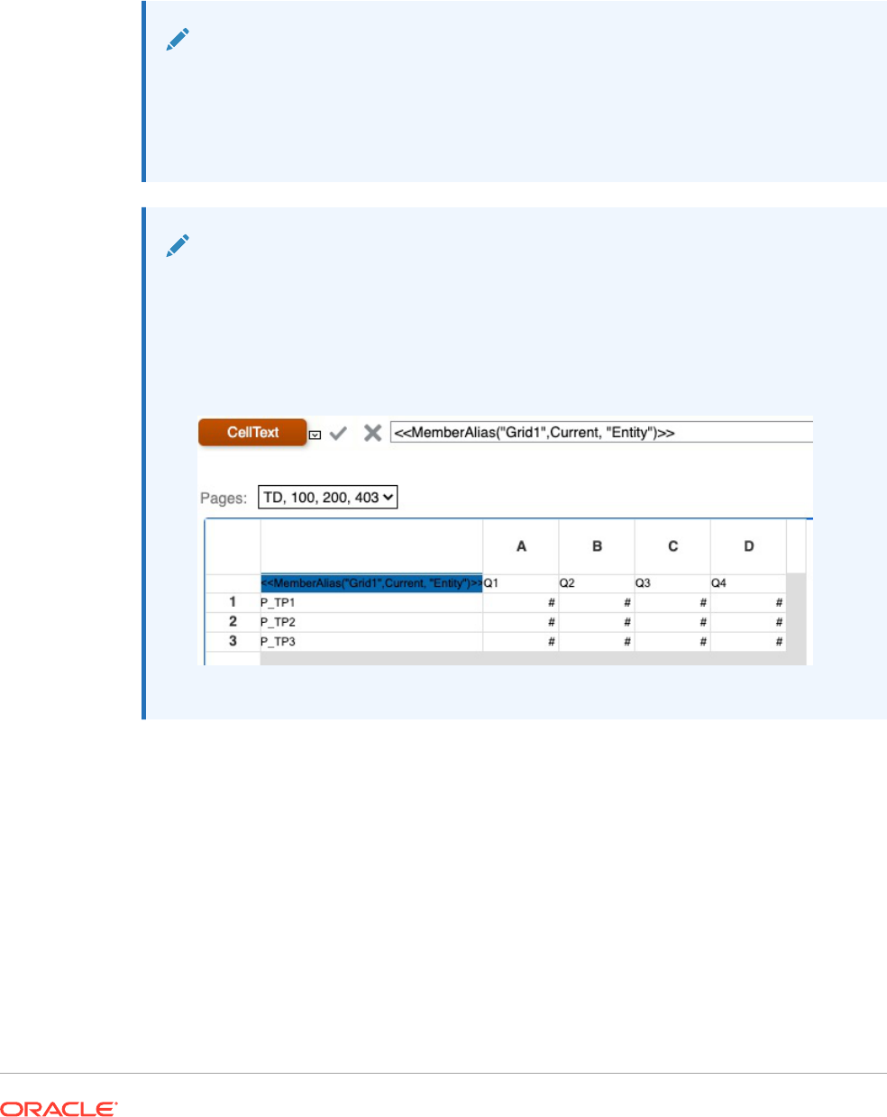
<<MemberAlias(current)>>
Yield the alias for the Scenario dimension for the POV associated with Grid1:
<<MemberAlias("Grid1", "Scenario")>>
<<MemberAlias(current, "Scenario")>>
Note:
MemberAlias
only supports the
Current
keyword when used in a grid cell or in a text
box object when specifying the Page dimension parameter. Other parameters (Grid,
Row, Column) are not supported in a text box object, header, or footer. See Using
the Current/Cur Keyword in a Text Function.
Note:
Using
MemberAlias
in cells that are not part of a row or column will not update when
referenced with a Page dimension.
In the following example,
MemberAlias
is in the column header, above the row
dimensions
<<MemberAlias("Grid1", Current, "Entity")>>
:
MemberName
MemberName
is a text function. Based on the syntax used, it returns the name of the member
assigned to a dimension in the row, column, page, or Point of View (POV).
• The following syntax returns the name of a row heading, column heading, or page. The
syntax can be deployed from any heading cell, text cell or text box object and can
reference any grid in a current report.
<<MemberName("GridName", Row/Col/Page, "DimName")>>
• The following syntax returns the name in a row heading, column heading, or page. The
syntax can be deployed from any row, column, or page heading in a grid that is
designated as a custom heading. To designate a custom heading, click the page, row
heading, or column heading, and then select Custom Heading on the property
sheet. You can add the function in the space provided below the custom heading.
<<MemberName(
"DimName")>>
• The following syntax returns the name of a grid or user POV. The syntax can be
deployed from any text cell or text box object and can reference any grid and
corresponding POV in a current report.
<<MemberName(
"GridName", "POV DimName")>>
Argument Description
GridName Name of the grid.
Row/Col/Page Numeric identifier of the row, the alphabetical identifier of the column, or the
numeric identifier of the page.
DimName Name of a dimension in the grid row, column, or page.
POV DimName Name of the dimension on the grid or user POV.
Examples:
Return the name assigned to the Product dimension in Grid1, column A:
<<MemberName("Grid1", A, "Product")>>
<<MemberName(current, A, "Product")>>
Return the name for the Year dimension. The syntax is placed on the grid’s custom
heading:
<<MemberName("Year")>>
Return the name for the Scenario dimension for the POV associated with Grid1:
<<MemberName("Grid1", "Scenario")>>
<<MemberName(current, "Scenario")>>
Note:
MemberName
only supports the
Current
keyword when used in a grid cell or in
a text box object when specifying the Page dimension parameter. Other
parameters (Grid, Row, Column) are not supported in a text box object,
header, or footer. See Using the Current/Cur Keyword in a Text Function.
Note:
Using
MemberName
in cells that are not part of a row or column will not update
when referenced with a Page dimension.
MemberProperty
Note:
MemberProperty
is applicable to Planning details and Oracle Essbase database
connections.
MemberProperty
is a text function. Based on the syntax used, it returns the member property
value of a dimension in the row, column, page, or Point of View (POV). You can use this
function to display a member property in a text row or column.
• The following syntax returns the member property of a row heading, column heading, or
page. The syntax can be deployed from any heading cell, text cell or text box object and
can reference any grid in a current report.
<<MemberProperty(
"GridName", Row/Col/Page, DimName, Property)>>
• The following syntax returns the member property in a row heading, column heading, or
page. The syntax can be deployed from any row, column, or page heading in a grid that
is designated as a custom heading. To designate a custom heading, click the page, row
heading, or column heading, then select Custom Heading on the property sheet. You can
add the function in the space provided below the custom heading.
<<MemberProperty
("DimName", Property)>>
• The following syntax returns the member property of a grid or user POV. The syntax can
be deployed from any text cell or text box object and can reference any grid and
corresponding POV in a current report.
<<MemberProperty
("GridName", POV DimName, Property)>>
Argument Description
GridName Name of the grid.
Row/Col/Page Numeric identifier of the row, the alphabetical
identifier of the column, or the numeric identifier of
the page.
POV DimName Name of the dimension on the grid or user POV.
Property Any custom property (attribute dimensions).
Examples:
Return the member property assigned to the Product dimension in Grid1, column A:
<<MemberProperty("Grid1", A, Product,Pkg Type)>>
<<MemberProperty(current, A, Product, Pkg Type)>>
Return the member property for the Market dimension. The syntax is placed on the grid’s
custom heading:
<<MemberProperty("Market", Population)>>
<<MemberProperty(current, Population)>>
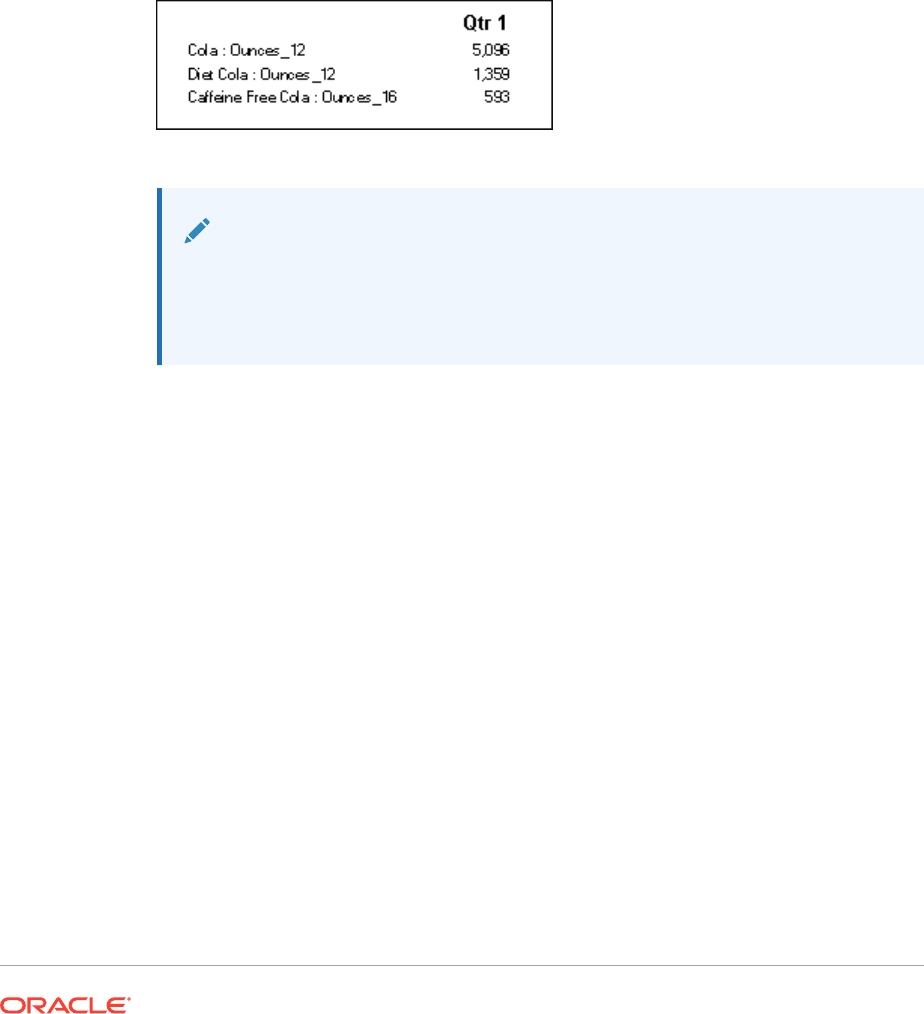
Return the member property for the Market dimension for the POV associated with
Grid1:
<<
MemberProperty("Grid1", Market, CurrencyCategory)
>>
<<
MemberProperty(current, Market, CurrencyCategory
)>>
Retrieve the Member Alias and Ounces property of a product in a custom heading. (To
do this, select the heading, then on the Heading Row Properties sheet, select the
Custom Heading option, and then click Functions).
<<MemberAlias(current, current, Product)>>:
<<MemberProperty(current, current, Product, Ounces)>>
The report output would resemble the following:
Note:
MemberProperty
only supports the
Current
keyword when used in a grid cell,
not in a text box object, header, or footer. See Using the Current/Cur
Keyword in a Text Function.
MemberQualifiedName
MemberQualifiedName
is a text function that, based on the syntax used, returns the
qualified name of a non-unique member assigned to a dimension in the row, column,
page, or Point of View (POV). A non-unique member is a child of multiple parents.
For example, if a member is named 100 and is a child of the
Product1
member and
the
Product2
member, then 100 is a non-unique member name.
MemberQualifiedName
shows the qualified names in reports. The qualified member names in this example
are
[Product1].[100]
and
[Product2].[100].
• The following syntax returns the name of a row heading, column heading or page.
The syntax can be deployed from any heading cell, text cell or text box object and
can reference any grid in a current report.
<<MemberQualifiedName("GridName", Row/Col/Page, "DimName")>>
• The following syntax returns the qualified name in a row heading, column heading,
or page. The syntax can be deployed from any row, column or page heading in a
grid that is designated as a custom heading. To designate a custom heading, click
the page, row heading or column heading, then select Custom Heading on the
property sheet. You can add the function in the space provided below the custom
heading.
<<MemberQualifiedName("DimName")>>
• The following syntax returns the name of a grid or user POV. The syntax can be deployed
from any text cell or text box object and can reference any grid and corresponding POV
in a current report.
<<MemberQualifiedName("GridName", "POV DimName")>>
Argument Description
GridName
Name of the grid.
Row/Col/Page
Numeric identifier of the row, the alphabetical identifier of the column, or the numeric
identifier of the page.
DimName
Name of a dimension in the grid row, column, or page.
POV DimName
Name of the dimension on the grid or user POV.
Examples:
Return the qualified non-unique name assigned to the Product dimension in Grid1, column A:
<<MemberQualifiedName("Grid1", A, "Product")>>
<<MemberQualifiedName(current, A, "Product")>>
Return the name for the Year dimension. The syntax is placed on the grid’s custom heading:
<<MemberQualifiedName("Year")>>
Return the qualified non-unique name for the Scenario dimension for the POV associated
with Grid1:
<<MemberQualifiedName("Grid1", "Scenario")>>
<<MemberQualifiedName(current, "Scenario")>>
Note:
MemberQualifiedName
only supports the Current keyword when used in a grid cell;
not in a text box object, header, or footer. See Using the Current/Cur Keyword in a
Text Function.
Page
Page
is a text function that returns the current page number of a printed report. Use this
function in a text object.
Syntax:
<<Page()>>
Example:
If the current page is eight, yield: Page 8.
Page<<PAGE()>>

Note:
Page
works for printed reports only. Online reports display
[[PageCount( )]]
for the page number. The page axis on a grid is different from the page
number in a printed report.
PageCount
PageCount
is a text function that returns the total number of pages in a printed report.
Use this function in a text object.
Syntax:
<<PageCount()>>
Example:
If the current page count is 6, yields: "The total number of pages is: 6".
The total number of pages is: <<PageCount()>>
Note:
PageCount
works for printed reports only. Online reports display
[[PageCount( )]]
for the page number.
PlanningAnnotations
PlanningAnnotations
is a text function that retrieves the critical notes or comments
associated with a cell’s Planning Unit from the Planning database connection.
Planning Units are a combination of Scenario, Version, and Entity and are derived in
Financial Reporting through cell references in a grid.
Syntax:
<<PlanningAnnotations("GridName", Row, Column, Page, Attributes, Range)>>
<<PlanningAnnotations("GridName", Row, Column, Page, Attributes)>>
Argument Description
GridName (Required) Name of a grid.
Row (Required) Numeric value representing the row number of the grid. The
first row in a grid has an index of 1, the second row has an index of 2,
and so on.
Column (Required) Letter that represents the column of the grid. The first column
in a grid has an index of A, the second column has an index of B, and so
on.

Argument Description
Page (Required) Numeric value representing the index of member
combinations on all page dimensions of the grid. The first page
dimension combination in a grid has an index of 1, the second page
dimension combination has an index of 2, and so on.
Attributes Any of the following values: All, Title, Author, Date, Text, PlanningUnit.
(PlanningUnit is the combination of scenario, version, and entity and is
derived from the GridName, Row, Column, and Page.)
Arrange attributes in the preferred order of output, and separate each
attribute with an ampersand (&).
Range Use the keywords All, Top, or Bottom. to select the number of annotations
from the top or bottom of an output, or all annotations.
•
All
returns all annotations
•
Top 5
returns the first five annotations
•
Bottom 10
returns the last ten annotations
•
Bottom 1
returns the last annotation
Example 1:
"All" is assumed for the Range parameter.
<<PlanningAnnotations("Grid Name", 1,a,1,All, All)>>
<<PlanningAnnotations("Grid Name", 100,AB,10,All, All)>>
<<PlanningAnnotations(cur, cur,a,cur,Text & Title & Author, Top 5)>>
<<PlanningAnnotations(cur, 315, AB, 255, Text&Title&Author, Top 5)>>
<<PlanningAnnotations(cur, cur A, Cur, PlanningUnit, Top 5)>>
<<PlanningAnnotations(cur, 123, ABC, 101, PlanningUnit, Top5)>>
<<PlanningAnnotations(Grid1, 1, current, cur, Title & Text, Bottom 10)>>
<<PlanningAnnotations(Grid1, 105, ABC, cur, Title & Text, Bottom 10)>>
<<PlanningAnnotations(Current, 34, BB, cur, All, Top 40)>>
<<PlanningAnnotations(cur, cur, A cur, Text & Title & Author, Top 5)>>
<<PlanningAnnotations(cur, cur, A, cur, Text&Title&Author, bottom15)>>
<<PlanningAnnotations(cur, 1(3), A(B), cur, Title&Author&Date&Text, All)>>
<<PlanningAnnotations(cur, 1(3), A(B), cur, Title&Author&Date&Text, All)>>
Example 2:
Retrieve annotation text in row 1, column A, of a grid on the current page. Display the bottom
three annotations and all attributes associated with the annotation (title, author, date, text,
and planning unit).
Use this syntax in a text cell:
<<PlanningAnnotations(Current, 1, A, Current, All, Bottom 3)
Annotations are returned chronologically in descending order by date, with the most recent
annotations on top and the oldest annotation on the bottom. The resulting annotation text
resembles the following:
Title: Status - Under Review
Author: John Smith
Date: Mar 25, 2003 10:32:49 AM
Planning Unit: Budget, 1st Draft, East
Text: Please review and approve
— — — — — — — — — — — — — — — — —
Title: Status - Not Signed Off
Author: Mary Brown
Date: Mar 21, 2003 2:59:11 PM
Planning Unit: Budget, 1st Draft, West
Text: Sorry, Try Again
— — — — — — — — — — — — — — — — —
Title: Status - Under Review
Author: Admin
Date: Mar 21, 2003 2:54:16 PM
Planning Unit: Budget, 1st Draft, South
Text: Please review and approve budget for 1st draft
Note:
PlanningAnnotations
only supports the
Current
keyword when used in a
grid cell; not in a text box object, header, or footer. See Using the
Current/Cur Keyword in a Text Function.
ReportAuthor
ReportAuthor
is a text function that returns the user name of the person who created
the report. Use this function in a text box, text cell, row, or column heading.
Syntax:
<<ReportAuthor()>>
Example:
Return the name of the report author:
<<ReportAuthor()>>
ReportCreated
ReportCreated
is a text function that returns the date a report was created. Use this
function in a text box, text cell, row, or column heading.
Syntax:
<<ReportCreated("format","TimeZoneId")>>
Argument Description
format Characters, enclosed in quotation marks, that define the format of the date and time.
Format defaults to the user preference for date /time. Valid values are those accepted
by Java
SimpleDateFormat
, "user", or empty ("user").
For a detailed description of date and time formats, see. Table 1.
TimeZoneId Defaults to user preferences for the time zone. Valid values are those accepted by Java
TimeZone.getTimeZone()
, or the server time zone.
For example, for
TimeZone.getTimeZone()
to specify the east coast, enter:
America/New_York
.
Note:
The date and time format is case-sensitive.
ReportCreated
returns a value only
after the report is saved.
Example:
Insert the report creation date in the body of a report:
<<ReportName()>>
- Created on
<<ReportCreated("d-MM-yy")>>
ReportDesc
ReportDesc
is a text function that returns the description of the current report. Use this
function in a text box, text cell, row, or column heading.
Syntax:
<<ReportDesc()>>
Example:
Insert a report description in the body of a report:
<<ReportDesc()>>
Note:
You can define a report description when you save the report. Afterward, you can
change the description in the repository or when you save the report again with the
Save As command.
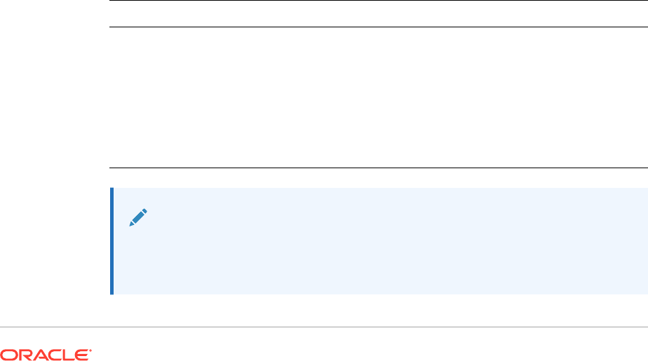
ReportFolder
ReportFolder
is a text function that returns the path of the folder where the report is
located. Use this function in a text box, text cell, row, or column heading.
Syntax:
<<Reportfolder()>>
Example:
Insert the path of the folder where the report is located:
<<Reportfolder( )>>
Considerations when using
ReportFolder
:
• The report must be located in a folder other than the root folder. The root folder is
not considered a report folder and returns an empty string.
• The report must be saved to a folder in order to return the correct string. An
unsaved report returns an empty string.
• If you open a report containing a
ReportFolder
function, save it to a new folder.
When you use Print Preview to preview the report, the previous location of the
folder is displayed. This is by design for performance reasons. To reevaluate the
report, modify a grid or report object, then use Print Preview to see the new folder
location.
ReportModified
ReportModified
is a text function that returns the date the current report was last
modified. Use this function in a text box, text cell, row, or column heading.
Syntax:
<<ReportModified("format","TimeZoneId")>>
Argument Description
format Characters, enclosed in quotation marks, that define the format of the date
and time. Format defaults to the user preference for date /time. Valid values
are those accepted by Java
SimpleDateFormat
, "user", or empty ("user").
For a detailed description of date and time formats, see Table 1.
TimeZoneId Defaults to user preferences for the time zone. Valid values are those
accepted by Java
TimeZone.getTimeZone()
, or the server time zone.
For example, for
TimeZone.getTimeZone()
to specify the east coast, enter:
America/New_York
.
Note:
The date and time format is case-sensitive.
ReportModified
returns a value
only after the report is saved.

Example:
Insert the date Jan 19, 2013. (This is the date that the report was last modified.)
Report Modified: <<ReportModified("MMM dd, yyyy")>>
ReportModifiedBy
ReportModifiedBy
is a text function that returns the user name of the last user to save the
report. Use this function in a text box, text cell, row, or column heading.
Syntax:
<<ReportModifiedBy()>>
Example:
Insert the name of the last user to save the report:
<<ReportModifiedBy()>>
ReportName
ReportName
is a text function that returns the name of the current report. Use this function in a
text box, text cell, row, or column heading.
Syntax:
<<ReportName()>>
Example:
Insert the report name:
<<ReportName( )>>
ReportRunBy
ReportRunBy
is a text function that returns the user name of the user who is running the
report. Use this function in a text box, text cell, row, or column heading.
Syntax:
<<ReportRunBy()>>
Example:
Insert the name of the user who is running the report:
<<ReportRunBy()>>

RetrieveValue
RetrieveValue
functions in existing reports are no longer supported and must be
manually updated to use the
GetCell
function.
Conditional Functions
When creating an If, Then, If conditional function, you can use conditional operators
and complex conditions.
Related Topics
• IFThen, If
• Conditional Operators
• Complex Conditions
IFThen, If
IfThen
is a conditional function that returns a value when the condition equals True,
and another value when the condition equals False.
Syntax:
IfThen(Condition, TrueParameter, FalseParameter)
• Condition is a logical expression that evaluates to true or false. Full conditional
logic can be used as well as complex Boolean operators (And, Not, and Or). A
condition can also test for #missing and #error values.
• TrueParameter and FalseParameter are expressions that are evaluated based on
the outcome of the condition.
Conditional Operators
When using conditional operators, consider the following:
• Expression can be any valid formula expression. The expression can be any
combination of a constant (integer or real number), a reference, or another
function.
• Reference can be any valid reference; thus the
IFNN
reference property can be
utilized as part of the reference.
• Condition can be any valid condition applied to the complex conditions And, Not,
and Or. These operators can have embedded conditions. (And, Not, and Or
operators require surrounding parentheses.)
• When any
expression
within the condition returns an #error or #missing value,
the
If
function returns #missing or #error. This does not apply when you use the
IsMissing
,
IsError
, or
IsNonNumeric
conditions.

Table 15 Conditional Operators
Conditional Operator Syntax Logic
Equal To expression
=
expression Tests if the left expression is equal to
the right expression.
Example:
1=4
Returns false
Note: If rounding is required, use the
Round
function.
Greater Than expression
>
expression Tests if the left expression is greater
than the right expression.
Example:
1 > 4
Returns false
Greater Than or Equal To expression
>=
expression Tests if the left expression is greater
than or equal to the right expression.
Example:
1>=4
Returns false
Note: The correct syntax is ">=". The
syntax "=>" is not supported.
Less Than expression
<
expression Tests if the left expression is less
than the right expression.
Example:
1<4
Returns true
Less Than or
Equal To
expression
<=
expression Tests if the left expression is less
than or equal to the right expression.
Example:
1<=4
Returns true
Note: The correct syntax is "<=". The
syntax "=<" is not supported.
Not Equal To expression
<>
expression
expression
!=
expression
Tests if the left expression is not
equal to the right expression.
Example:
1<>4
Returns true
1!=4
Returns true
Note: If rounding is required, use the
Round
function.

Table 15 (Cont.) Conditional Operators
Conditional Operator Syntax Logic
IsMissing
IsMissing (
reference
)
IsMiss (
reference
)
Tests if the reference contains a
#missing result.
Example:
IsMissing([1])
Returns true if row 1 has a #missing
value.
Note: If the reference is an
expanded row or column, then all
resulting cells must be #missing in
order for the condition to be true.
IsError
IsError (
reference
)
IsErr (
reference
)
Tests if the reference contains an
#error result.
Example:
IsError([2])
Returns true if row 2 has a #error
value.
Note: If the reference is an
expanded row or column, all resulting
cells must be #error in order for the
condition to be true. Only formula
rows and columns can result in
#error.
IsNonNumeric
IsNN (
reference
)
IsNonNumerid (
reference
)
IfNN (
reference
)
IfNonNumber (
reference
)
Tests if the reference contains a
#missing or #error results.
Example:
IsNN([3])
Returns true if row 3 has a #missing
or #error value.
Note: If the reference is an
expanded row or column, all resulting
cells must be #missing and/or #error
in order for the condition to be true.
Parenthesis
(
condition
)
Groups a condition.
Example:
(1 > 4)
Returns false
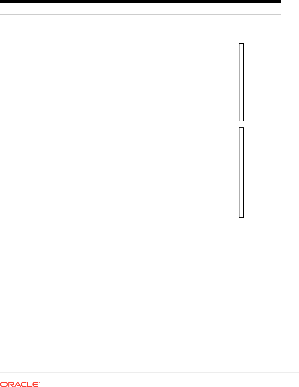
Complex Conditions
Table 16 Complex Conditions
Complex Conditions Syntax Logic
And
(
condition
AND
condition
)
(
condition
&
condition)
Compares two conditions. Returns
true if all conditions are true.
Example:
(
1
>
4
A
N
D
5
>
2
)
R
e
t
u
r
n
s
f
a
l
s
e
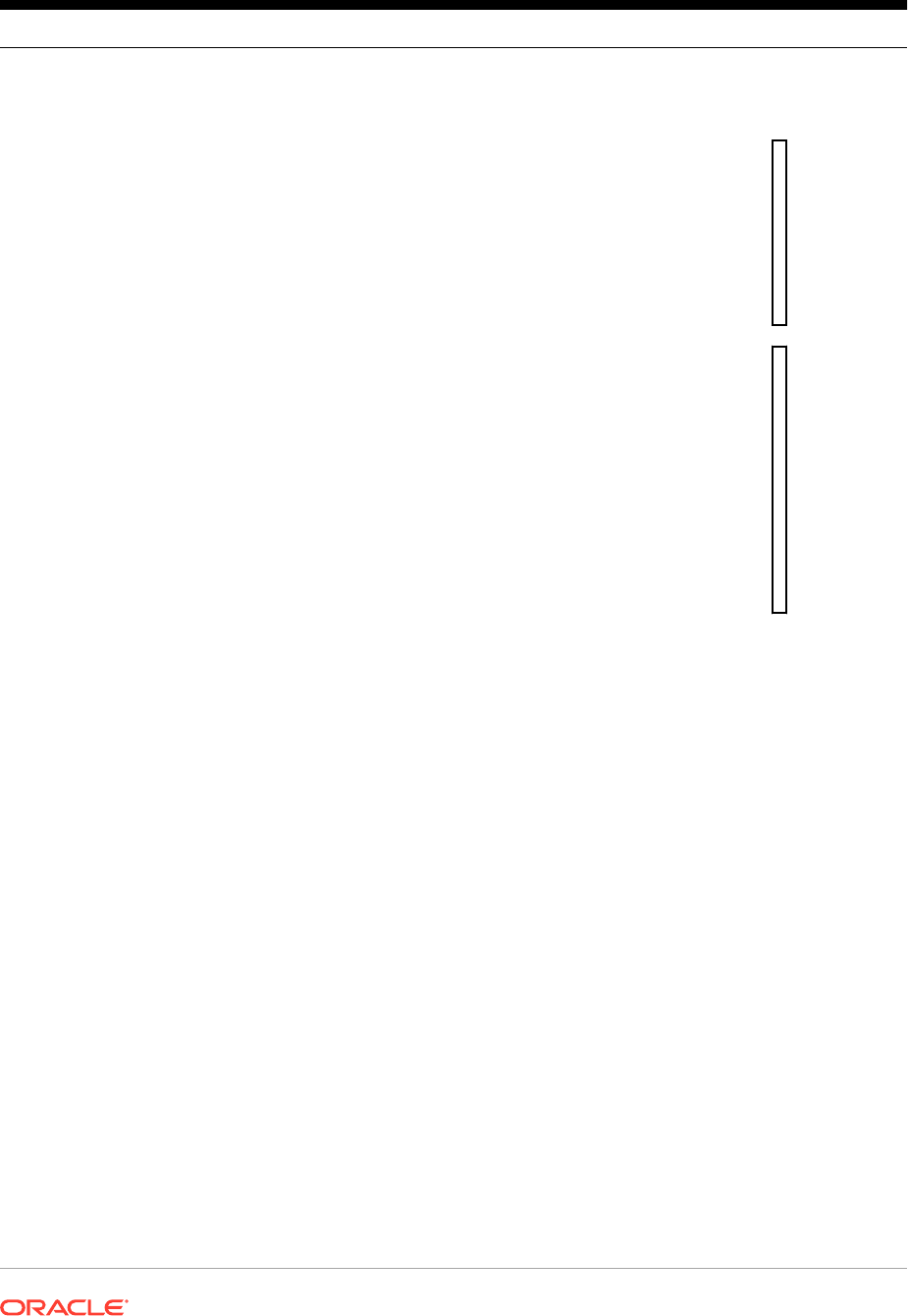
Table 16 (Cont.) Complex Conditions
Complex Conditions Syntax Logic
Not
NOT (
condition
)
! (
condition
)
Negates the result by reversing the
result of the condition.
Example:
N
o
t
(
1
>
4
)
R
e
t
u
r
n
s
t
r
u
e
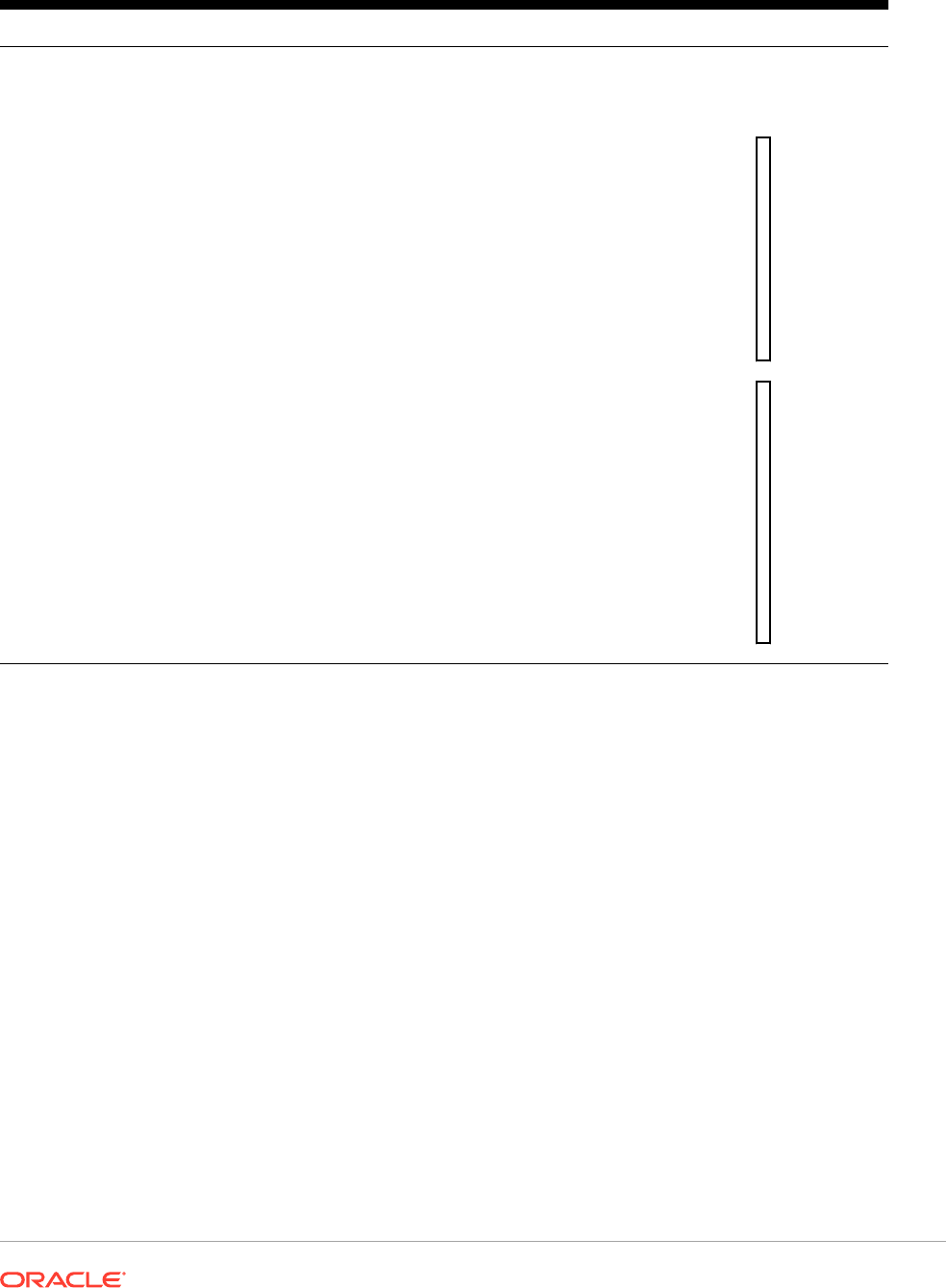
Table 16 (Cont.) Complex Conditions
Complex Conditions Syntax Logic
Or
(
condition
OR
condition
)
(
condition
|
condition
)
Compares two conditions. Returns
true if any of the conditions are true.
Example:
(
1
>
4
O
R
5
>
2
)
R
e
t
u
r
n
s
t
r
u
e
Complex conditions And, Or, and Not are fully supported. However, they must be surrounded
by parentheses.
Valid example:
If ( ([A] > [B] and [A] > 1000), [A], [B])
Invalid example:
If ( [A] > [B] and [A] > 1000, [A], [B])
Financial Functions
Financial functions include
Rank
,
Variance/Var
, and
VariancePercent/VarPercent
.
Related Topics
• Rank
• Variance/Var
• VariancePercent/VarPercent
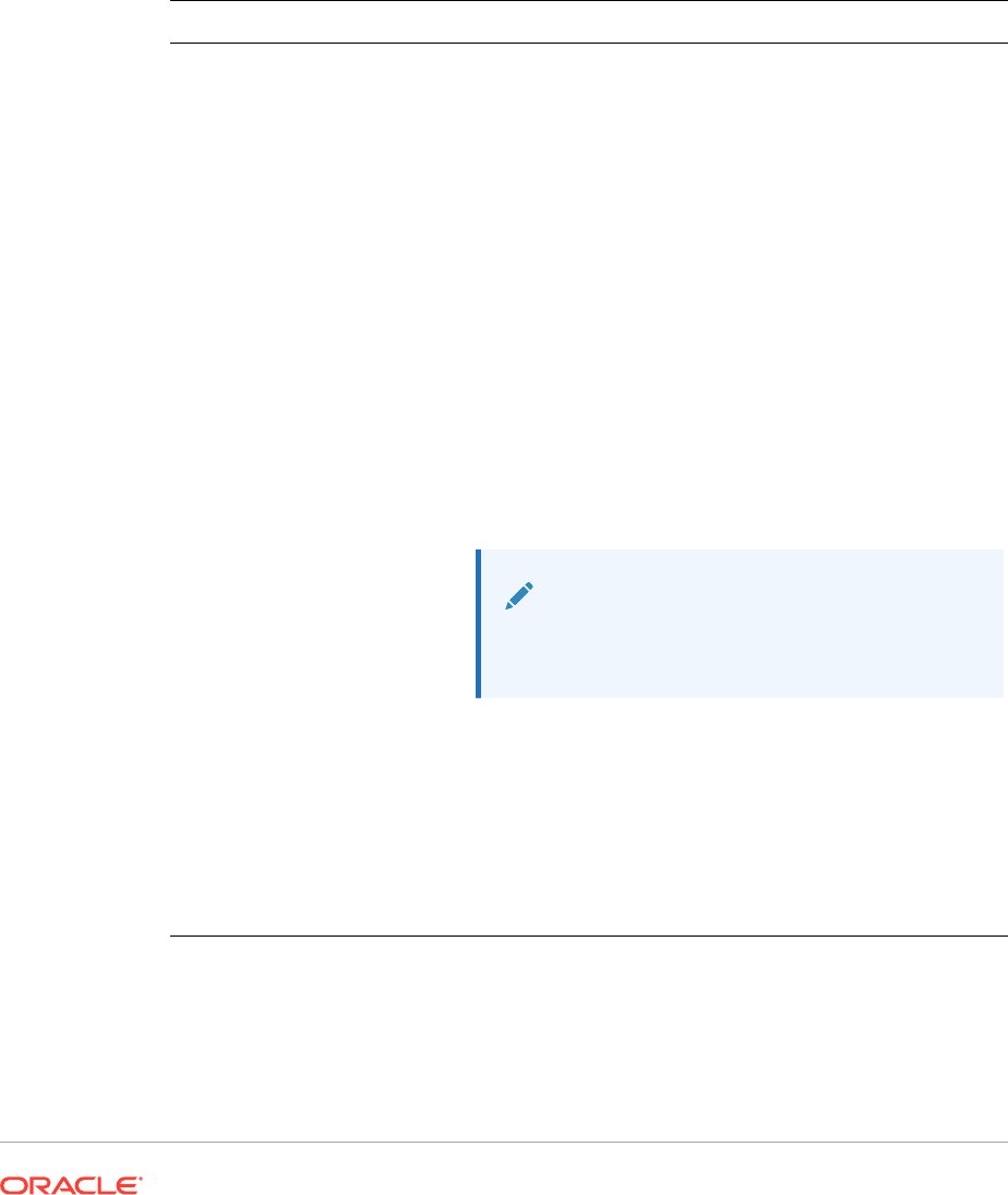
Rank
Rank
is a financial function that provides a rank value for a value in a specified range.
Rank
is processed by Financial Reporting and does not depend on the database
connection.
Syntax:
Rank([Reference], Order)
Rank([Reference], Order, Unique)
Argument Description
Reference The range of cells, rows, or columns to rank, with letters identifying columns
and numbers identifying rows. For example, specify [A,1:5] to rank the values
for rows 1 through 5 in column A.
You can use the .ifNN property with a range of cells to assign numbers to any
cells with nonnumeric values so that those cells can be ranked. For example,
you can use .ifNN(-1) to assign the value -1 to any cell with a missing value.
Order Indicates the order by which the values are ranked. The lowest value ranked in
ascending order receives a rank result of 1. The largest value ranked in
descending order receives a rank result of 1. The order can be indicated by any
of the following keywords or values:
• Ascending
• Descending
• Asc
• Des
• Desc
• 1 (the number 1 is the same as Ascending)
• 0 (zero is the same as Descending)
The keywords are not case-sensitive.
Note:
Do not enclose the number or keyword indicating
order in quotation marks.
Unique (Optional) A Boolean keyword indicating how to treat equal values in the
Reference parameter where:
•
false (or omitted) — equal values receive the same ranking ; ranked
results may be duplicated
•
true — equal values receive a unique ranking; there are no duplicate
rankings. Values in the Reference parameter are ranked on a first come,
first ranked basis. For example, if values in rows 2 and 5 are equal, the
value in row 2 is ranked before that of row 5.
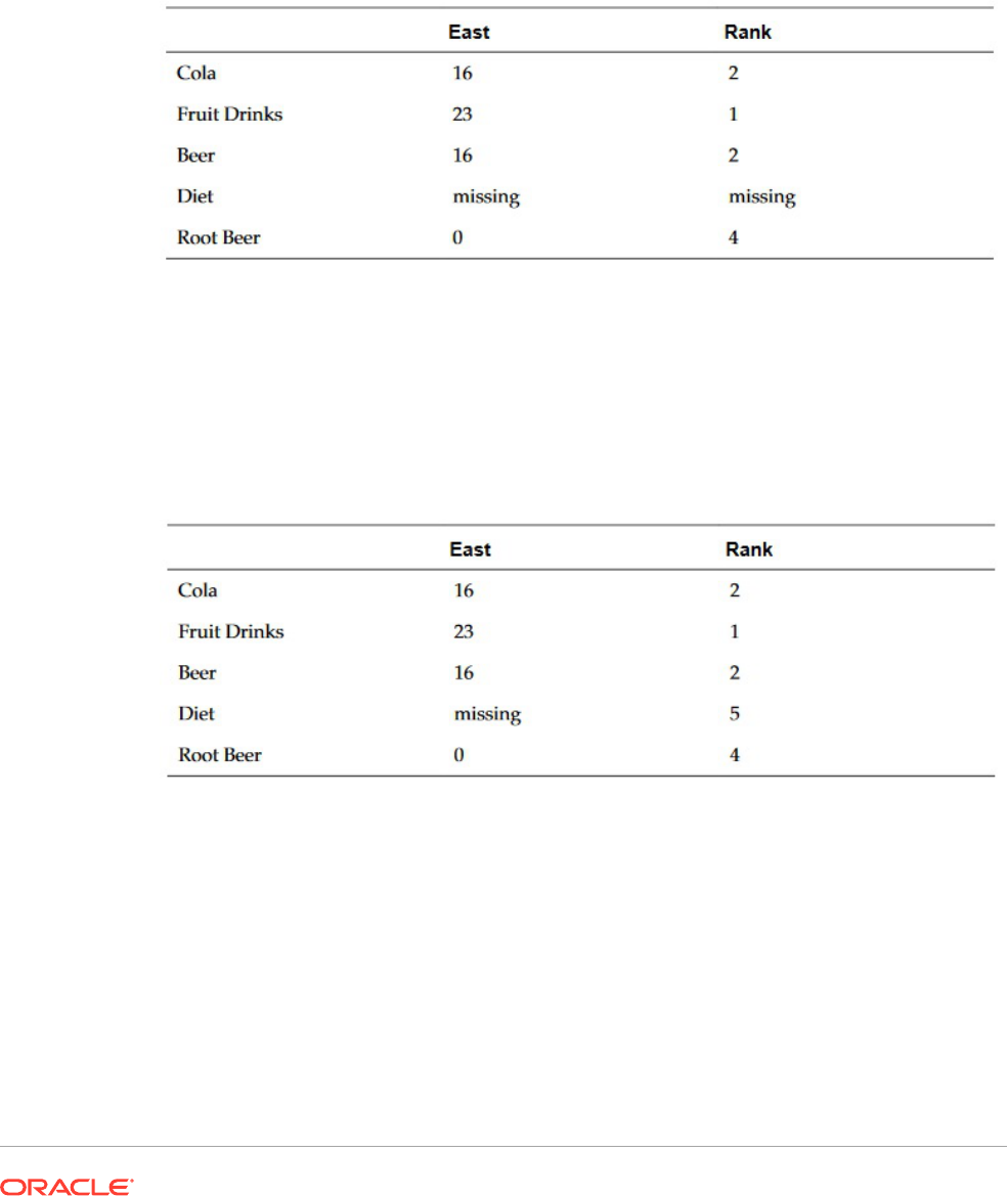
Examples:
This formula in column B ranks the values in rows 1 through 5 in column A in descending
order:
Rank([A,1:5], descending)
The result might be as follows:
When two values are equal, they receive the same rank value. In the example above, Cola
and Beer have the same value and therefore the same rank.
This formula in column B assigns the value of -1 to any nonnumeric value so it can be
ranked:
Rank([A,1:5].ifNN(-1), descending)
In the following result, the missing value now has a rank of 5:
Example:
The following example builds on the previous example explaining how the new "unique"
parameter affects the results:
This formula in column B assigns the value of -1 to any nonnumeric value so it can be
ranked, and also indicates that each ranking should be unique:
Rank([A,1:5].ifNN(-1), descending, true)
In the following result, the missing value now has a rank of 5, and Beer has a value of 3
(even though it has the same data value as Cola):
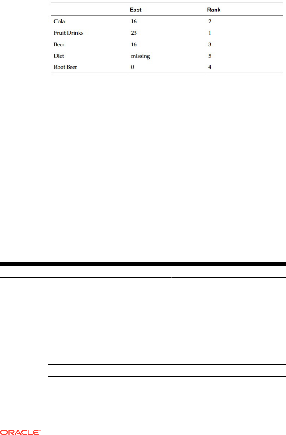
Variance/Var
Variance/Var
is a financial function that evaluates the difference between the
specified values based on account type for the current account.
For Expense accounts, a positive result represents an unfavorable variance, so the
result appears as a negative number. For Non-expense accounts, a positive result
represents a favorable variance, so the result appears as a positive number.
Variance/Var
is available for standard database connections in PBCS, EPBCS, or
FCCS.
Syntax:
Var(reference1, reference2)
where
reference1
and
reference2
are references to a row, column, or cell that
correspond to members of the same Account dimension whose variance results are to
be calculated.
Expected Results
Table 17 Expected Results When Using
Variance/Var
Column A Column B Var ([A] , [B])=0 Var ([A] , [B])>0 Var ([A] , [B])<0
Expense Expense 0 Returns a negative
value
Returns a positive
value
Non-Expense Non-Expense 0 Returns a positive
value
Returns a negative
value
Variance Behavior
Variance
expects comparison of the same account type. When you compare two
different account types, like Sales & Expense,
Variance
performs the math without
applying the logic of the account type. For example:
Sales
Expense Result
-400 100 -500

Examples
Variance
accepts cell, column, or row references only. For more information, see Row,
Column, or Cell Reference Arguments.
Syntax Example
Sample syntax referencing a
column:
Var ([A], [B])
Sample syntax referencing a
row:
Var ([3], [4])
Sample syntax referencing a
cell:
Var (Cell [3,A], [3,B])
In this example, the variance between column A (Actual) and column B (Budget) is
calculated as:
Var([A],[B])
This example produces the following report:
Year Product Market
Actual Budget Variance
======== ======== ========
Sales(Income) 400,855 373,080 27,775
COGS (Expense) 179,336 158,940 -20,396
VariancePercent/VarPercent
VariancePercent/VarPercent
is a financial function that evaluates the difference, in percent,
between the specified values based on account type for the current account.
For Expense accounts, a positive result represents an unfavorable variance, so the result
appears as a negative number. For Non-expense accounts, a positive result represents a
favorable variance, so the result appears as a positive number.
Variance/Var
is available for standard database connections in PBCS, EPBCS, or FCCS.
Syntax:
VarPer(reference1, reference2)
where
reference1
and
reference2
are references to a row, column, or cell that correspond
to members of the same Account dimension whose
VariancePercent
results are calculated.
Expected Results
Table 18 Expected Results When Using
VariancePercent/VarPercent
Col A Col B VarPer ([A] , [B])=0 VarPer ([A] , [B])>0 VaPer ([A] , [B])<0
Expense Expense 0 Returns a negative
value
Returns a positive
value
Non-Expense Non-Expense 0 Returns a positive
value
Returns a negative
value
VariancePercent Behavior
VariancePercent
expects comparison of the same account type. When you compare
two different account types, like Sales & Expense, the
VariancePercent
function
performs the straight math without applying the logic of the account type. For example:
Sales Expense Result
-400 100 -5.
• #missing is treated as zero (0), unless specified differently using
ifnonnumber
property.
• #error is results in #error, unless specified differently using
ifnonnumber
property.
Examples
VariancePercent
accepts, cell, column, or row references only. See Row, Column, or
Cell Reference Arguments.
Syntax Example
Sample syntax
referencing a column:
VarPer ([A], [B])
Sample syntax
referencing a row:
VarPer ([3], [4])
Sample syntax
referencing a cell:
VarPer (Cell [3,A], [3,B])
In this example, the
VariancePercent
between column A (Actual) and column B
(Budget) is calculated as follows:
VarPer([A],[B])

This example produces the following report:
Year Product Market
Actual Budget VariancePercent
======== ======== ========
Sales(Income) 400,855 373,080 7%
COGS (Expense) 179,336 158,940 -13%

Part III
Administrative Tasks
Related Topics
• Uploading Custom Fonts
You can upload custom fonts to the Financial Reporting server.
• Managing Server Settings
Server values are Financial Reporting server-side settings and properties that control
global behavior for Financial Reporting reports.
• Managing Log Configurations
If you need to contact customer support about an issue in Financial Reporting, you can
set TRACE level logging to generate the UDR/SAR with detailed logging information.
• Managing the User Point of View
Use Financial Reporting Web Studio to import, export, or delete the user point of view for
one or more users.
• Cleaning Up Orphan Report Objects
When you clean up orphan report objects, any report objects not associated with a data
source are deleted from the Explore Repository.
Uploading Custom Fonts
You can upload custom fonts to the Financial Reporting server.
When you upload a custom font, the following restrictions apply:
• Only true type fonts (.tff) are supported.
• You can only upload one font at a time.
• The font's embeddability property must be set to installable.
To determine if a font is installable, in Windows Explorer, right-click the font, and then
select Properties. In the Properties dialog box, select the Details tab, and then check
the "Font Embeddability."
Note:
When uploading custom fonts, you are responsible for meeting the Terms of Service
for the fonts, and you should license them accordingly. Oracle does not guarantee
that an uploaded font will work, and Oracle is not liable if a font is misused.
To upload a custom font:
1. Select File, then Manage, and then Fonts.
2. In the Fonts dialog box, click .
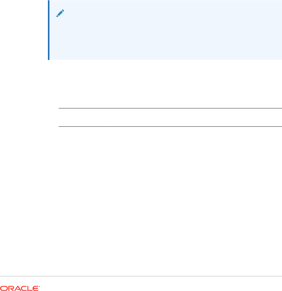
3. In the Upload Font dialog box, click Browse, and then select the true type (.ttf)
font to upload.
To select which columns to display in the Fonts dialog box, select View, and then
Columns. To reorder the columns displayed, select View, and then Reorder
Columns.
4. In the Fonts dialog box, click OK to save the font.
The font is now available to select as you design your reports in Financial
Reporting Web Studio.
Managing Server Settings
Server values are Financial Reporting server-side settings and properties that control
global behavior for Financial Reporting reports.
Service Administrators can edit Server settings in Financial Reporting Web Studio.
Note:
• Report Designers cannot change Server settings.
• Server settings are not available in the Fusion edition of Financial
Reporting Web Studio.
To edit Server settings in Financial Reporting Web Studio:
1. Select File, then Manage, and then Server.
2. In the Settings tab, edit the following properties:
Property Name Default
Value
Description
Missing Values in
Formulas as Zero
false Whether to treat missing values as zero in formula
calculations.
• When set to false, missing values are not the same
as zero values in formula calculations.
• When set to true, missing values are treated as a
value of zero in formula calculations.
Display Member
Selection Filter in
Workspace
Preferences
true
Changes the
FilterBySecurity
settings in the
Financial Reporting preferences for the User POV.
• When set to false, users cannot change the
FilterBySecurity
settings, and cannot see
members to which they lack access.
• When set to true, users can change the
FilterBySecurity
settings in the Financial
Reporting User POV preferences and can see
members to which they lack access.
Add Timestamp
Sux for Batch
Output File
true Species whether to add the timestamp sux to the
batch output le when bursting batch reports.

Property Name Default
Value
Description
Maximum
Iterations for
Calculations
10 Species the maximum number of calculation
iterations for all grids and cells. (Valid values are 1
through 9.)
During the calculation process of a grid, it may be
necessary to evaluate a cell multiple times due to
reference precedence. This mostly occurs in grids with
references to other grids. If there are no circular
references and calculation cells are retuning an error,
increasing the value may resolve the problem.
Note: A high number may degrade grid execution
performance.
Number of
Decimals for Zero
2 How many decimal places a number must have before
it is considered a zero (0). (Valid values are 1 through
9.)
Number of
Decimals for Zero
in Suppression
5 How many digits to the right of the decimal place are
evaluated when determining if a numeric value is zero
in conditional suppression and conditional formatting.
(Valid values are 1 through 9.)
When you do conditional suppression/format against a
‘Value’ of ‘0’, the value to absolute zero (0) is compared.
For example, using the default property of 5, a value of
0.00001 is considered zero.
Maximum
Number of Page
Members for
Excel Export
100
Species the maximum number of page dimension
members that can be exported to Excel.
Maximum E-mail
Attachment Size
10 Maximum size of e-mail attachments when e-mailing
books using the Batch Scheduler.
Chart Plotting
Ignores Data
Values
none Denes how charts treat #MISSING, #ERROR, and
#ZERO values.
• NONE: Do not display #MISSING, #ERROR, and
#ZERO values in the chart.
• ERROR: Display a plotted value as zero for #ERROR
values in the chart.
• ZERO: Display a plotted value as zero for #ZERO
values in the chart.
• MISSING: Display a plotted value as zero for
#MISSING values in the chart.
• ERROR & MISSING: Display a plotted value as zero
for #ERROR and #MISSING values in the chart.
• ERROR & ZERO: Display a plotted value as zero for
#ERROR and #ZERO values in the chart.
• MISSING & ZERO: Display a plotted value as zero
for #MISSING and #ZERO values in the chart.
• MISSING & ZERO & ERROR: Display a plotted value
as zero for #MISSING, #ZERO, and #ERROR values
in the chart.
Related Content
URL Launch
Mode
post Denes the type of HTTP request made for related
content URLs.
The default launch method is HTTP post. In scenarios
where the related content URLs do not support a post
request, change the server setting to HTTP get.

Property Name Default
Value
Description
Export to Excel
Using Default
Sheet Name
false Controls Excel sheet names upon export.
• When set to false, the sheet name uses the
Financial Reporting report name.
• When set to true, the sheet name uses the Excel
default name (Sheet1, Sheet2, etc.)
Export to Excel
Ignoring Page
Breaks
true Denes how page breaks are handled when exporting
reports to Excel.
• When set to true, reports are exported to Excel as a
single sheet, ignoring page break denitions in the
report.
• When set to false, reports are exported to Excel as
multiple sheets based on page break denitions in
the report.
Export to Excel in
One Sheet
false Denes how to export physical pages from Excel.
• When set to true, physical pages are exported into a
single Excel sheet.
• When set to false, physical pages are exported into
separate sheets.
Export Physical
Pages to Excel in
Multiple Sheets
false Denes how to export Financial Reporting reports with
multiple physical pages to Excel, where a physical page
is the same as a single page in PDF preview.
• When set to true, reports with multiple physical
pages are exported to different sheets.
• When set to false, reports with multiple physical
pages are exported to one sheet.
Cleanup Batch
Jobs Older Than
never Denes how long a batch job and its les are retained
in the repository before being deleted. Options include:
• Never
• 7 days
• 15 days
• 20 days
• 30 days
Batch Cleanup
Process Interval
never Denes the interval between batch cleanup. Options
include:
• Never
• 7 days
3.
Click OK.
Managing Log Configurations
If you need to contact customer support about an issue in Financial Reporting, you can
set TRACE level logging to generate the UDR/SAR with detailed logging information.
To set TRACE level logging:
1. Select File, then Manage, and then Log Configuration.
2. In the Log Configuration dialog box, click the drop-down and select TRACE:32
for any of the following:
• oracle.EPMADM

• oracle.EPMFR
• oracle.EPMFR.frwebstudio
• oracle.EPMFR.jsp
• oracle.EPMJCR
3. Click OK
4. When you have finished, return to the Log Configuration dialog box, and set the log
information back its original setting.
Managing the User Point of View
Use Financial Reporting Web Studio to import, export, or delete the user point of view for one
or more users.
Related Topics
• About Managing the User Point of View
• Exporting User POVs from Financial Reporting
• Importing User POVs into Financial Reporting
• Deleting User POVs in Financial Reporting
• Use Case: Managing POVs for Multiple Users
About Managing the User Point of View
In Financial Reporting, users have a user point of view for each data source that they can
access. Administrators can import, export, or delete the user point of view for one or more
users.
To change user POVs for multiple users and data sources, you modify and import an XML file
that contains the POVs for users and data sources. The easiest way to create the layout of
the XML file is to export the user POVs from Financial Reporting. You then modify the XML
file and import the user POVs back into Financial Reporting.
Administrators can also delete POVs for multiple users and data sources if the user POVs
are corrupt. User POVs can be corrupt due to changes to data source outlines, such as
adding, removing, or renaming dimensions.
Note:
In order to import, export, or delete POVs, you must ensure that the User Point of
View preference is set to On in the Financial Reporting, General preferences. To do
this, open the Explore Repository, and select File, and then Preferences.
Exporting User POVs from Financial Reporting
To export user POVs from Financial Reporting into an XML file:

1. Log in to Financial Reporting Web Studio as an administrator.
2. Select File, then Manage, and then User Point of View.
3. Enter the following information in the User Point of View dialog box:
• Action: Select Export.
• User Names: Enter the user names to export. Separate each user name with
a comma. To export all users, leave the field empty.
• Data Sources: Select the data sources to export. To export all the valid
available data sources, select All or leave the field empty.
4. Click Submit.
5. Click OK in the confirmation dialog box.
6. Verify that the export was successful,, and then click Close to close the dialog box
The POVs for the selected user names and data sources are exported to an XML file.
You can view and modify the XML file before importing the POVs back into Financial
Reporting.
Importing User POVs into Financial Reporting
To import user POVs from an XML file into Financial Reporting:
1. Log in to Financial Reporting Web Studio as an administrator.
2. Select File, then Manage, and then User Point of View.
3. Enter the following information in the User Point of View dialog box:
• Action: Select Import.
• User Names: Enter the user names to import. Separate each user name with
a comma. To import all users, leave the field empty.
• Data Sources: Select the data sources to import. To import all the valid
available data sources, select All or leave the field empty.
4. Click Browse, and then open an XML file contains the user POVs; for example,
ManageUserExportPOV.xml
.
5. Click Submit.
6. Click OK in the confirmation dialog box.
7. Verify that the import was successful,, and then click Close to close the dialog box
The POVs for the selected user names and data sources are imported into Financial
Reporting.
Deleting User POVs in Financial Reporting
To delete user POVs in Financial Reporting:
1. Log in to Financial Reporting Web Studio as an administrator.
2. Select File, then Manage, and then User Point of View.
3. Enter the following information in the User Point of View dialog box:
• Action: Select Delete.

• User Names: Enter the user names to delete. Separate each user name with a
comma. To delete all users, leave the field empty.
• Data Sources: Select the data sources to delete. To delete all the valid available
data sources, select All or leave the field empty.
4. Click Submit.
5. Click OK in the confirmation dialog box.
6. Verify that the deletion was successful,, and then click Close to close the dialog box
Use Case: Managing POVs for Multiple Users
In this use case, we will complete the following steps:
In the Explore Repository:
• Set preferences for the user POV for two users
• Log on as each user and select an entity for each POV
In Financial Reporting Web Studio:
• Export and save the user POV file and confirm that the selected members are listed
below the user name
• Delete the user POV and view the confirmation message
• Import the exported XML file and view the confirmation message that the POVs have
been imported
In the Explore Repository, log on as each user and check the user POVs.
Set Preferences for the User POV
To set preferences for the user point of view:
1. Open Explore, and select File. and then Preferences.
2. In the Financial Reporting General tab, set the User Point of View to On, and then click
OK.
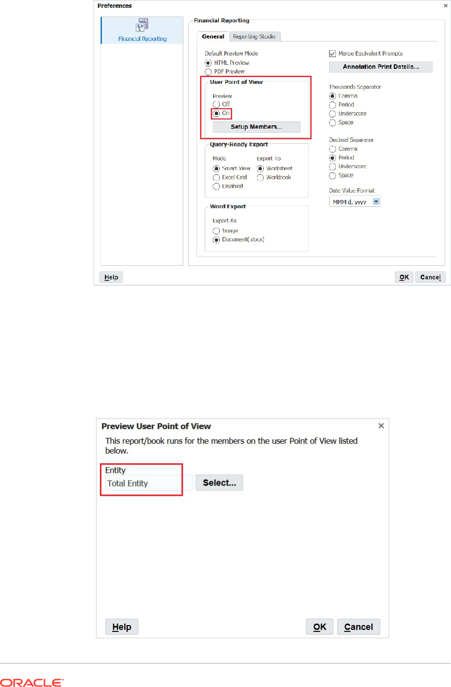
Select an Entity for Each User POV
To select an entity for a user POV:
1. In Explore, open a report containing a user point of view.
2. In the Preview User Point of View dialog box, select an entity, and then click OK.
In this example, we selected Total Entity.

3. Preview report and confirm that the entity you selected is on the POV.
In this example, Total Entity is on the POV.
4. Close Explore and log off.
5. Log on again as the second user, set the User Point of View to On, and repeat steps 1-3
but select a different entity as the POV.
In this example, we will select TD as the entity.
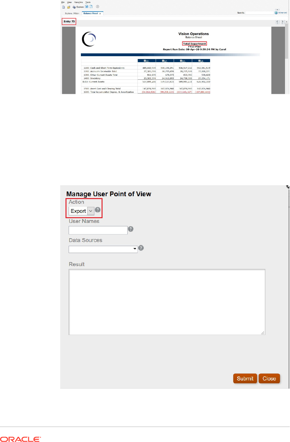
6. Close Explore and log off.
Export the User POVs from Financial Reporting to an XML File
To export the user POVs to an XML file:
1. Open Financial Reporting Web Studio , and select File, then Manage, and then
User Point of View.
2. In the Manage User Point of View dialog box, select Action, and then Export.
3. Select Submit.
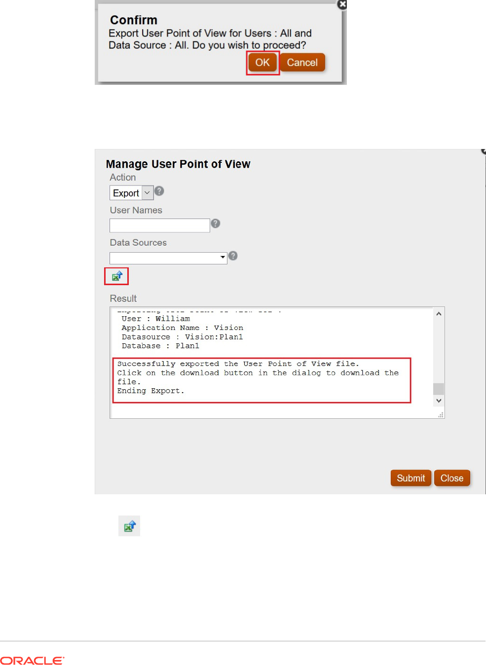
4. Click OK in the Confirm dialog box to proceed.
The status of the export in displayed in the Results section of the Manage User Point of
View dialog box. Scroll to the bottom to ensure that the export was successful.
5. Click (Download POV icon).
6. Select Save File to save the
ManageUserPOVExport.xml
file, and then click OK.
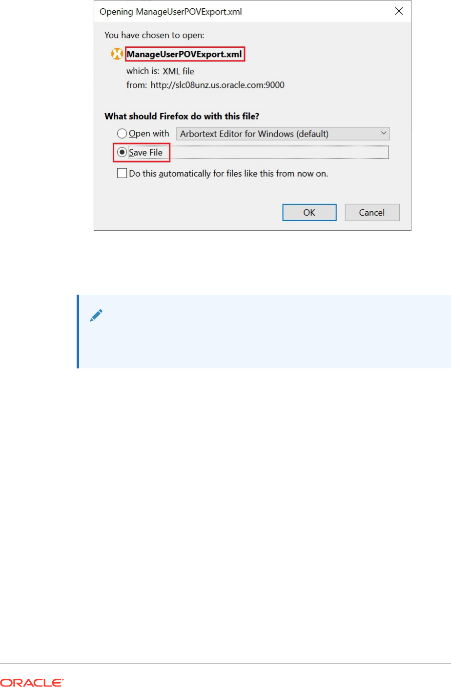
7. Select a location to save the file, and then click Save.
8. Open the
ManageUserPOVExport.xml
file you just saved, and view the user POVs.
Note:
At this point, you could modify the user POVs in the XML file before
importing them back in to Financial Reporting.
Delete the User POVs
To delete the user POVs,
1. In the Manage User Point of View dialog box, select Action, and then Delete.
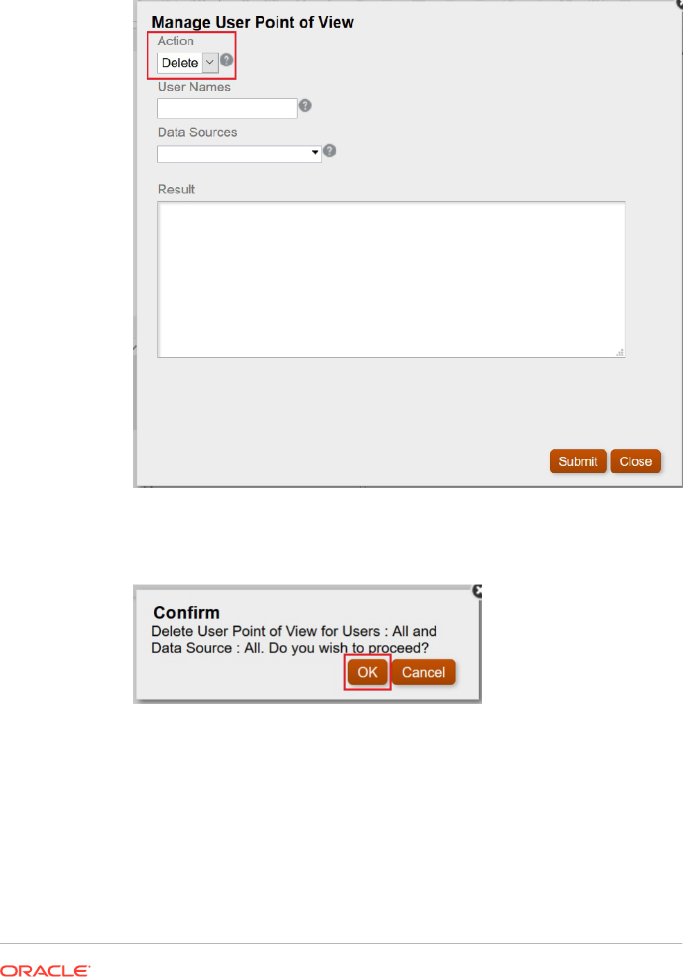
2. Select Submit.
3. Click OK in the Confirm dialog box to proceed.
The results should show the successful deletion of the POVs.
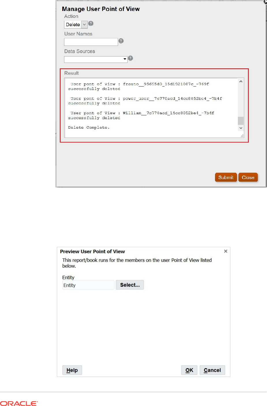
4. Click Close to close the dialog box.
5. Return to the Explore Repository, open the report containing the point of view, and
verify that there is no POV selected for Entity.
The Preview User Point of View dialog box should look as follows:
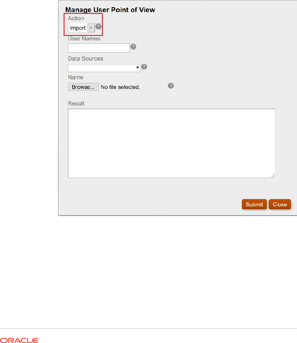
Import the Exported XML File back into Financial Reporting and Confirm the POVs
To import the exported XML file and confirm the POVs:
1. In Financial Reporting Web Studio , select File, then Manage, and then User Point of
View.
2. In the Manage User Point of View dialog box, select Action, and then Import, and
confirm that the Result section is emptied of content.
3. Click Browse, then open the
ManageUserExportPOV.xml
file that was exported earlier,
and then click Submit.
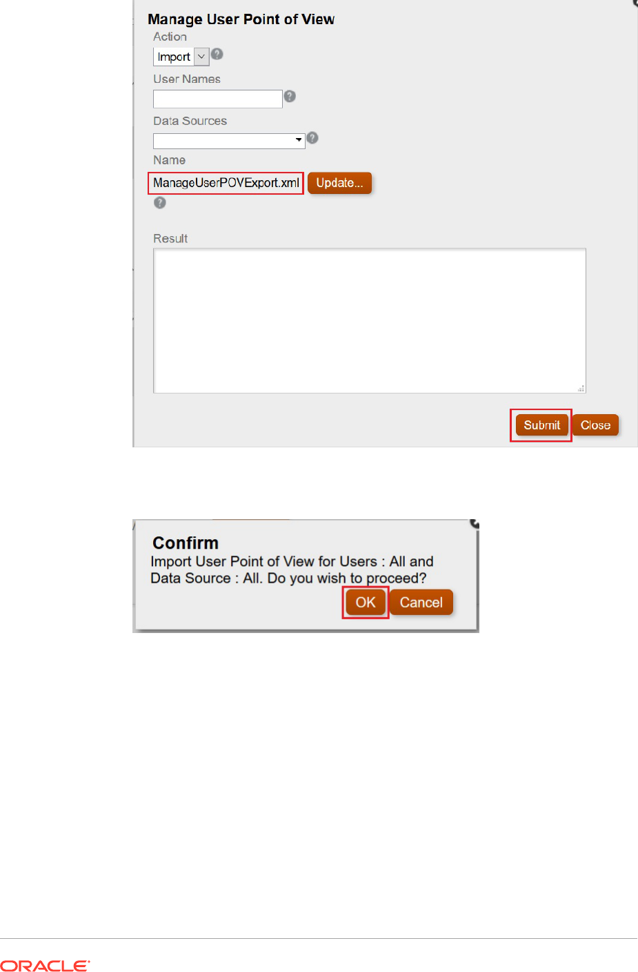
4. Click OK in the Confirm dialog box to proceed with the import.
5. Verify that the import was successful,, and then click Close to close the dialog
box.
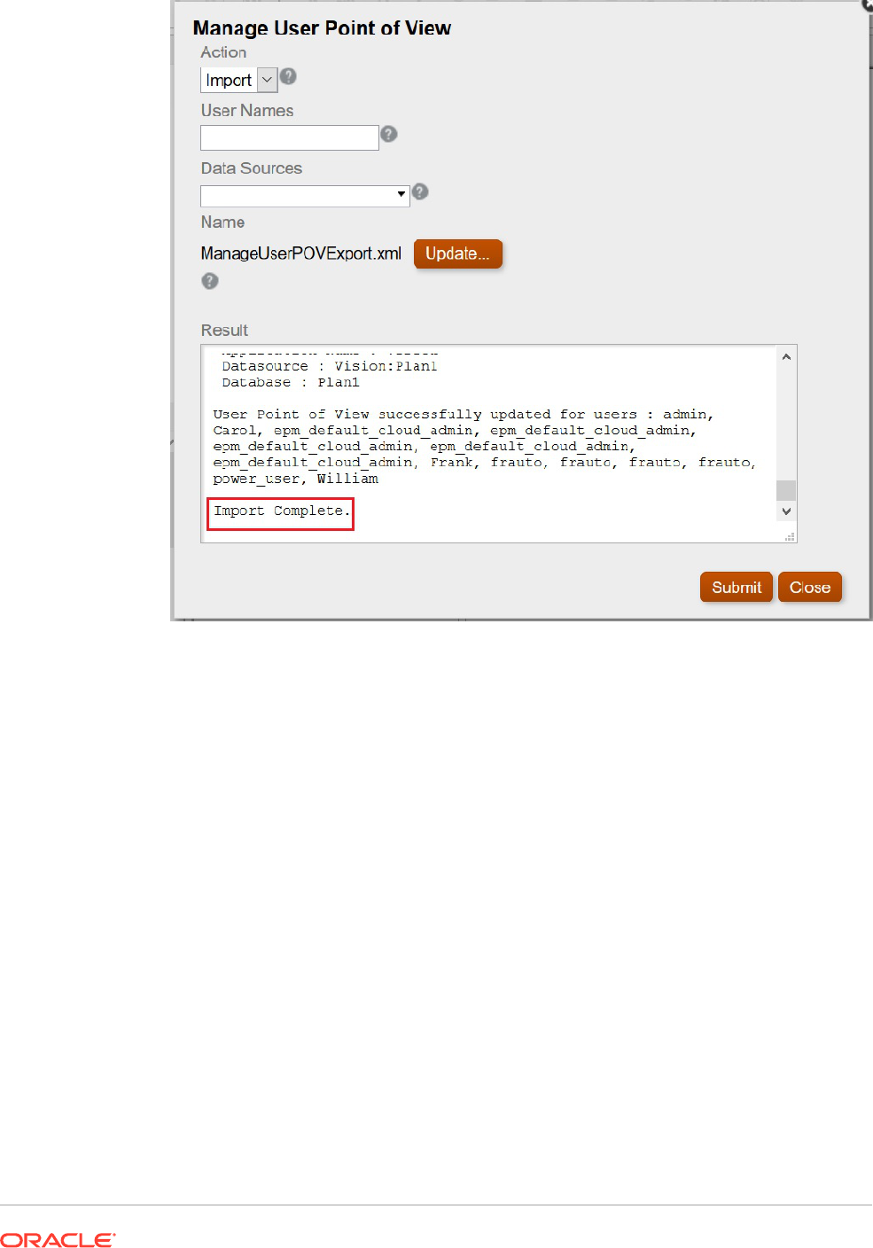
Log on As Each User and Verify the POVs
To log on as each user and verity the POVs:
1. In Explore, open the report.
2. In the Preview User Point of View dialog box, verify that the POV is displayed.
In our example, we defined POVs for Total Entity and TD.
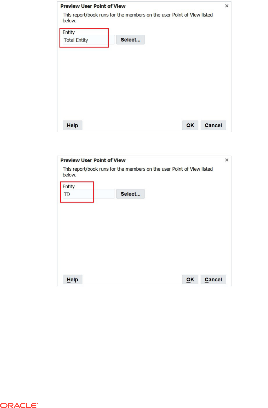
Cleaning Up Orphan Report Objects
When you clean up orphan report objects, any report objects not associated with a
data source are deleted from the Explore Repository.
You should only clean up orphan report objects if there are discrepencies between the
reports listed on the Home page and in the Explore Repository and Financial
Reporting Web Studio.
To clean up report objects:

1. In Financial Reporting Web Studio, select File, then Manage, and then Cleanup Orphan
Report Objects.
2. Click OK in the Confirm dialog box to confirm that that you want to proceed with the
cleanup.
Note:
This action cannot be undone. Once completed, a list of deleted objects is
displayed shown in a dialog and registered in the Financial Reporting.
